2.1.2.4 More information on topple

Topple:

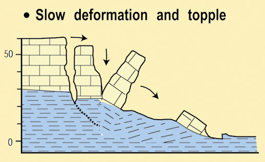
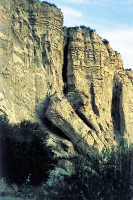
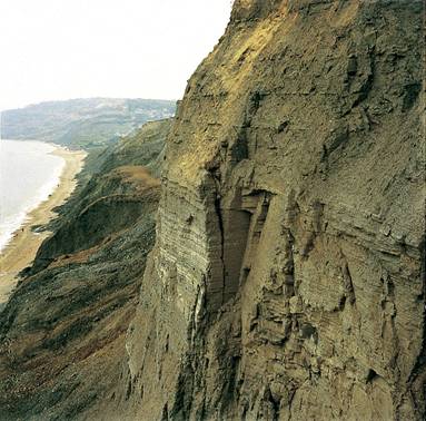
The movement is due to stresses which cause a toppling momentum around a rotation point situated below the centre of gravity of the rock mass affected. The phenomenon can evolve into either a fall or slide.

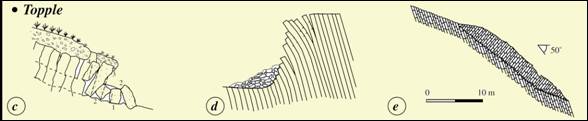
What is a topple phenomenon?

(Extract from Maquaire and Malet, 2006)

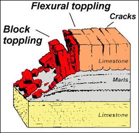
Topples (and also falls) comprise a free movement of material from steep slopes or cliffs. A topple is very similar to a fall in many aspects, but normally involves a pivoting action rather than a complete separation at the base of the failure.

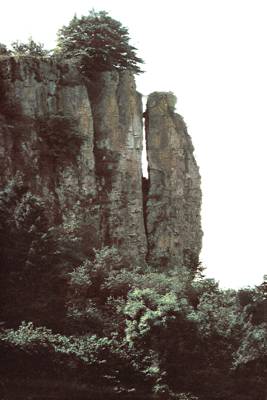
Their general characteristics are as follows: the shape of the rupture surface is usually smooth and vertical; the material falls suddenly from a main scarp following a preparation phase during which a slice of material is separated, damaging the intact mass; the volume and size of the fallen material are extremely variable, depending on the morpho-structural and lithological conditions of the slope. These phenomena occur on cliffs when the base is eroded by the action of the sea or of rivers. The falls are always sudden and very quick, while topples vary in speed from extremely slow to extremely quick, with acceleration and deceleration phases (Maquaire and Malet, 2006).

Fig. 1: Different types of topple (from Maquaire and Malet, 2006 adapted from Cruden and Varnes, 1996; Dikau et al., 1996;)

A topple is the forward rotation of a mass of rock or soil about an axis located below the centre of gravity of the displaced mass (Figure 1.c). Topples may lead to falls or slides of the displaced mass, depending on the geometry of the rupture surface and the orientation and extent of the kinematically active discontinuities. Cruden and Varnes (1996) state that the way in which topples occur may be very varied: flexural toppling occurs in rocks with one preferred discontinuity system, oriented to present a rock slope with semi-continuous cantilever beams which may develop into retrogressive complex rock topple-rock fall (Figure 1.d); block toppling occurs where the individual columns are divided by widely-spaced joints; chevron toppling occurs along complex structural configuration, where the change of dip is concentrated at the surface of rupture to give a complex rock topple-rock slide (Figure 1.e).

Fig. 2: Typical block diagram of a topple (from Dikau et al., 1996)
Fig. 3: Topple in limestone Rheinland-Pflaz, Germany (from Dikau et al. 1996)
Fig. 4: Toppling failure at Vera, Almeria, Spain (from Dikau et al. 1996)
Fig. 5: Tension crack toppling affecting sea cliffs at Stonebarrow Hill, West Dorset, UK (from Dikau et al., 1996)

References:

For the references herein and for knowing sources of didactic material go to 1.3 Selected references