Prevention of landslides in general, comprises several successive stages.
- Investigations must be carried out in order to identify the sectors prone to slide.
- These investigations lead to slide hazard assessment.
- Then, elements at risk are identified and their vulnerability is assessed in order to include slide hazard in territorial planning.
The result is a zoning map which defines terrains which can be built or not, according to the degree of hazard and vulnerability.
Prevention of subsidence, as for landslides in general, corresponds to a step comprising several successive stages sometimes requiring adapted techniques to seek cavities. The following stages are classically retained:
- Preliminary recognition allows an identification of the sectors prone to subsidence.
- Detection of the voids starting from a selection of specific hazard zones (achieved in stage 1), to precisely locate voids and decompressing zones (surfaces and volume)
Techniques of prevention
The main implication for a planner is to ensure that there are suitable surveys of areas which are likely to produce falls. These surveys are carried out by engineering geologists and geomorphologists. The purpose of these is the identification of the sectors prone to fall. It is possible with research of surface indices such as distribution of fissures and pattern of rock discontinuities.
As concern rock avalanches, with advanced investigations and development of predictive models it is possible to identify some of the likely areas for failure and to gain some idea of the possible run-out distance for a given volume. The identification of the sectors prone to topple is possible with research of surface indices such as open cracks.
These investigations lead to fall hazard assessment. Then, elements at risk are identified and their vulnerability is assessed in order to include fall hazard in town planning. The result is a zoning map which defines terrains which can be built or not, according to the degree of hazard and vulnerability (see more information on landslide mapping). Monitoring systems should also be installed in high risk areas.
Techniques of protection
These techniques can be only used for reducing controllable and small-scale fall hazards. In high-risk and large-scale cases there is generally no technical solution. These sites require to be continuously monitored. In France, the “Ruines de Séchilienne” rockfall, near Vizille (Isère) is a good example of monitoring strategy in combination with urban planning.
Techniques of protection can be classified in two distinct categories:
– “Active techniques”: they avoid the triggering of the fall. They mainly consist in reinforcement systems which retain the material (rock or soil) on the steep slope or the cliff.
– “Passive techniques”: they seek to control the consequences of the fall. They aim at interposing a “screen” between the steep slope and vulnerable elements.
A. Active techniques:
– Steel reinforcement
Reinforcement systems add strength to the rock mass by increasing the general tensile strength and by improving its resistance to shear along discontinuities. Both active and passive steel reinforcement systems are used for stabilizing rock slopes. The active system involves tensioned or prestressed bars or cables that have been anchored at one end within the rock mass by mechanical means or by cement or chemical grouts or by both. The passive system involves untensioned bars that have been fully grouted throughout their length by cement or chemical grouts. The main advantage of the active system over the passive system is that no movement has to take place before the anchor develops its full capacity; thus, deformation and possible tension cracking of the slope are minimized. Long-term corrosion protection of the anchors must be provided.
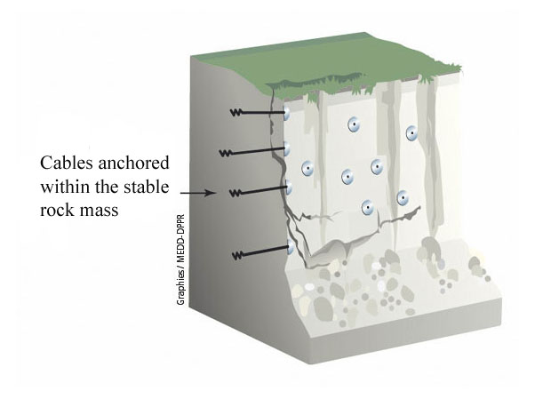
Length of bars or cables can vary from few meters to several tens of meters. Rock bolts are commonly used to reinforce the surface and near-surface rock of the slope. Tendon and cable anchors are used for supporting large masses of unstable rock and are accordingly longer than rock bolts. Short reinforcing bars fully grouted into the rock mass are commonly called dowels. Their action is somewhat similar to rock bolts.
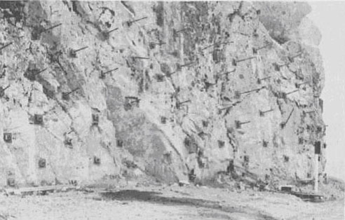
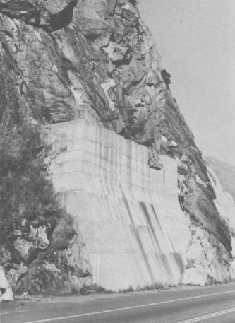
The rock bolt exerts a compressive force, which tends to prevent elastic rebound, frost action phenomena, and general relaxation or exfoliation by keeping the rock in its original position. Shear resistance along discontinuities is improved. Rock bolts are often used to minimize the decompression or loosening effects associated with recently excavated rock slopes. Figure 2 shows a group of large diameter bolts concentrated on an area at the base of a slope to maintain the integrity of large fault blocks.
– External support systems
They offer resistance to loads imposed by the slope-forming materials.
Buttresses and bulkheads are designed to take part of the weight of the slope, thus inducing stable conditions and preventing rock falls. They are used for stabilization where failure of overhangs appears to be imminent or where slight cracking or vertical displacement appears to be occurring. Buttresses are usually constructed at highway or railway level.
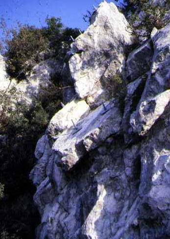
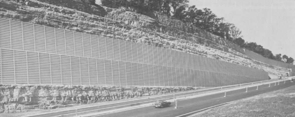
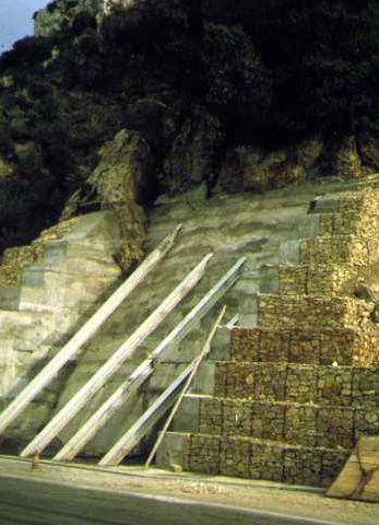
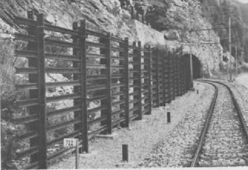
Retaining walls are used to prevent large blocks in the slope from failing and to control or correct failures by increasing the resistance to slope movements. The space along railways and highways is often too narrow for normal gravity walls, but tied-back walls may be used to overcome this problem. They need only have the strength required for bending and shear resistance between rock bolts. Figure 5 shows an application of a tieback retaining wall formed of galvanized steel members for protection of a high sedimentary road cut.
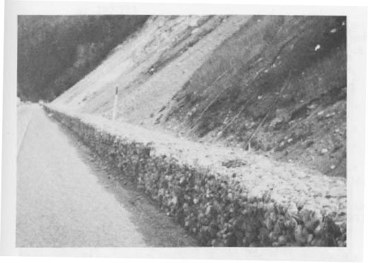
The box gabion catch wall is a rectangular basket divided by diaphragms into smaller rectangles that are filled with stones. The basket is formed of hexagonal steel galvanized wire mesh. The wire mesh tends to reinforce the stone in tension. The gabion is a flexible structure that tends to deflect and deform instead of breaking by rock impact. Gabion catch walls are recognized as a feasible alternative to more rigid concrete walls for protecting the roads from rolling stones as large as 0,6 to 1 meter.
– Shotcrete
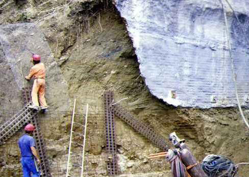
It is a concrete that consists of mortar with aggregate and that is projected by air jet directly onto the surface to be treated. It is used to prevent weathering and spalling of rock surfaces and to provide surface reinforcement between blocks. The shotcrete acts as a protective membrane on the surface of the rock and helps to maintain the adjacent rock blocks in place by mean of its initial shear and tensile strength. Shotcrete can be used in combination with steel wire mesh and rock bolts to give structural support and also to form buttresses for small loads (figure 9).
The most important advantage of shotcrete in treating rock slopes is that offers a rapid, mechanized and often uncomplicated solution to rock fall problems. Deterioration of shotcrete can result from frost action, groundwater seepage, or rock spalling due to lack of shotcrete bond.
– Rock face purge
Instable rock or fall is artificially caused. The aim is to obtain a bare rock face and thus to eliminate fall risks. Different techniques are used to cause the fall, such as mining, chemical grout into boreholes, hydraulic breaking out, etc. Purge is a temporary protection technique because the bare rock will be submitted to fragmentation phenomena, frost action, and will be more liable to fall again. Therefore, rock face purge requires regular monitoring.
B. Passive techniques:
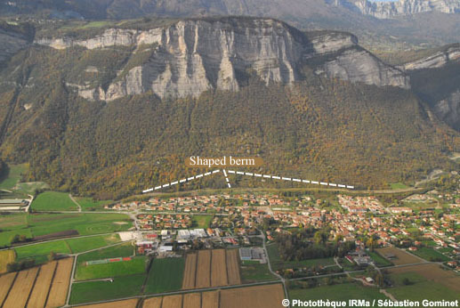
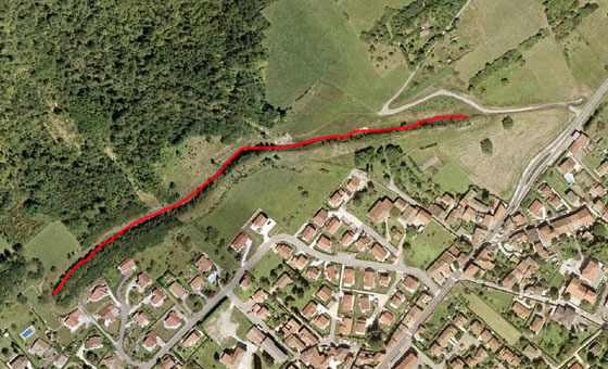
– Intercepting slop ditches and shaped berms
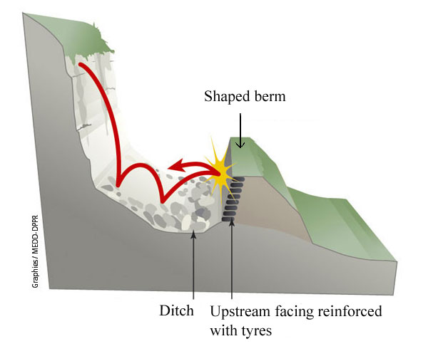
Slope ditches are used to intercept rock falls partway up the slope. Shaped berms are used at the top of the slope or can be installed in combination with a ditch. These methods ensure that rock falls get caught while they are on their way down the slope. The shaped berm is generally 4-6 m high, material (soil) is compressed and upstream face is often reinforced with gabions or tyres (figure 10). Depending of the nature of the terrain, ditches and berms are generally simple to construct and easy to maintain. An intercepting slope ditch should only be installed on a slope that can accept the introduction of a ditch without the stability of the entire slope being impaired.
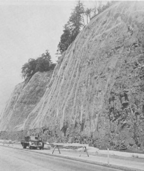
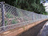
– Anchored wire mesh
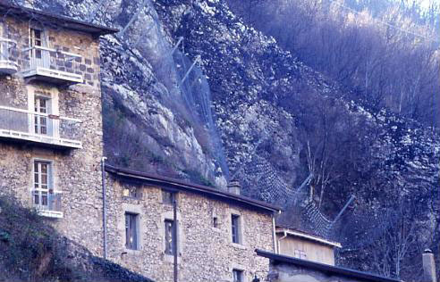
It is a versatile and economical material for use in protecting the right-of-way from small rocks. Layers of mesh are often pinned onto the rock surface and installed as a drapery to prevent small loose rocks from becoming dislodged. They also can be used to guide falling rocks into a ditch at the base of the slope. This practice is commonly used on talus slopes in steep mountainous terrain. Mesh can be combined with long rock bolts to provide a generally deeper reinforcement. Conditions for the use of mesh are particularly suitable if no individual rocks are larger than 0,6 to 1 meter and if the slope is uniform enough for the mesh to be in almost continuous contact with the slope.
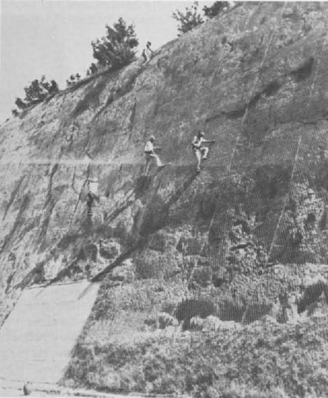
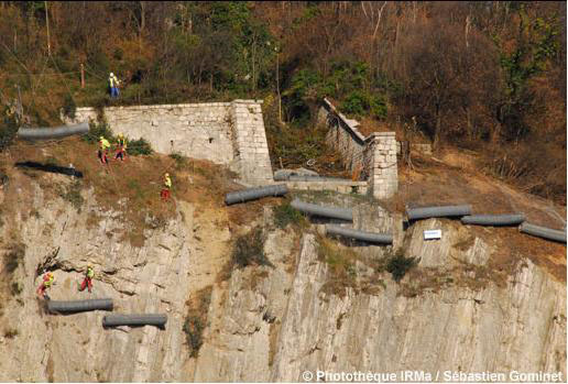
Anchored wire mesh can be installed at toe of rock face or on the slope and not only as a drapery onto the rock surface. They aimed at dissipating the kinetic energy of the rolling rocks and stopping their trajectory.
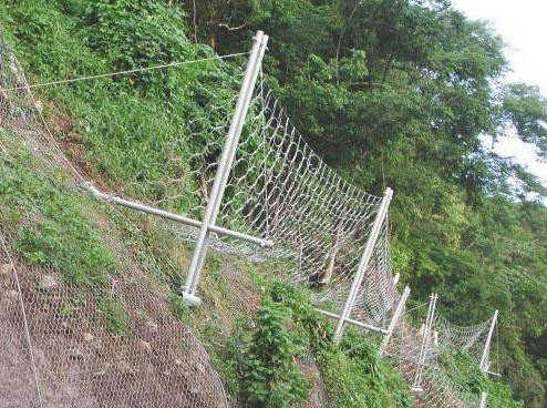
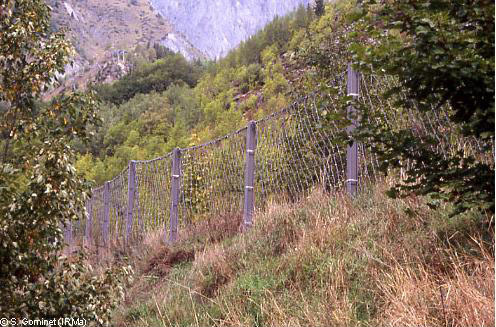
– Rigid fences
Rail walls consist of vertical posts and horizontal members that are extended between the vertical posts. The posts are usually scrap steel rails set in holes backfilled with concrete. The horizontal members are either ties or scrap rails. These rigid protection systems are generally less efficient than flexible screen such as wire mesh.
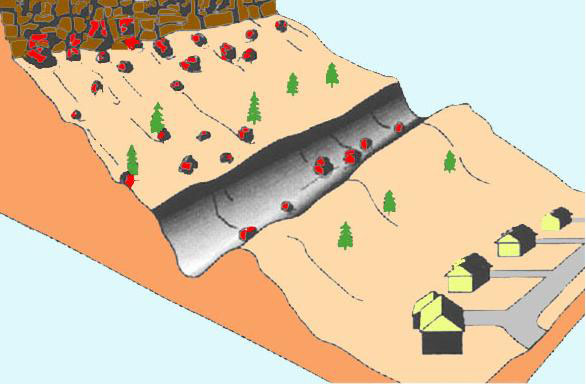
– Role of forest
Vegetation has positive and negative effects on slope stability (More information on landslide causes). Within the framework of fall risk prevention, forest can act as a natural barrier to intercept rolling rocks.
A team of researchers of Grenoble, in France, is currently working about the protection function of forest against rock fall hazard. Different in situ experiments are led to reconstruct natural rock fall and rocks trajectory. Trajectory modelling will be developed, in order to be used by local practitioners.
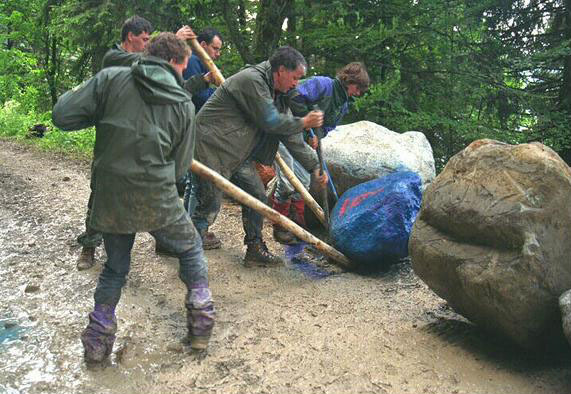
First studies showed that for a slope between 25 and 35°, forest plays an important protection role, stopping 80 % of rocks. Protection effect of forest acts on stop distance and bounce height of rocks. An experiment has been led with a 3 tons boulder rolling at 80 km/h with 2,5 meters high bounces. Forest stopped the boulder 80 meters further. Researches are also led with different tree species. Such studies contribute to develop long-term strategies for natural hazards prevention.
References:
– BESSON L., 2005. Les risques naturels: de la connaissance pratique à la gestion administrative. Editions Techni. Cités, Voiron, 60 p.
– BRUNSDEN D., PRIOR D., 1984. Slope instability. John Wiley & Sons Ltd, Chichester
– DIKAU R., BRUNSDEN D., SCHROTT L. & IBSEN M.-L. (eds.), 1996. Landslide Recognition: Identification, Movement and Causes. John Wiley & Sons Ltd, Chichester
– MATE, METL, 1997. Plans de prévention des risques naturels prévisibles (PPR). Guide général. La Documentation française, Paris, 76 p.
– NATIONAL RESEARCH COUNCIL, 2004. Partnerships for reducing landslide risk. Assessment of the landlide hazards mitigation strategy. The National academies press, Washington DC
– SLOSSON E., KEENE A.G., JOHNSON J.A., 1992. Landslides/Landslide mitigation. In: Reviews of Engineering Geology, Volume IX, Colorado
– TRANSPORTATION RESEARCH BOARD, 1978. Landslides: Analysis and Control. National Academy of Sciences, Special Report 176, Washington DC
Websites:
www.irma-grenoble.com
www.prim.net
Techniques of prevention
Flows processes analysis is complex because it concerns both geotechnics, geomorphology domains (as for landslides in general) and hydraulics domain. Thus, prevention and protection techniques must also concern these different domains.
Flow triggering is mainly caused by heavy rainfalls; prevision of rain falls events is possible thanks to predictive models, however they concern large areas and not small watersheds in which flows occur. Moreover, flows events are characterized by the rapidity with which they propagate in response to a rain fall event. Thus, prediction of flow events is difficult or even impossible.
The best way for flow prevention as for landslides in general is to control urbanization by a zoning map which defines terrains which can be built or not, according to the degree of flow hazard and vulnerability (see more information on landslide mapping).
Moreover, prevention techniques consist in regularly maintaining the main channel and the banks in order to avoid blocking of the channel by trees for example, liable to aggravate the consequences of the flow.
Techniques of protection
A flow is generated because of a great quantity of material is available for sediment transport on the slopes of the watershed. According to this, techniques of protection can be classified in two distinct categories:
– “Active techniques”: they avoid the triggering of the flow. They mainly consist in reducing sediment transport by acting on source areas, by reducing slope erosion processes.
– “Passive techniques”: they seek to control the consequences of the flow. They mainly consist in slowing down the flow by acting on the stream channel.
A. Active techniques
– Role of vegetation
It is admitted by scientific community that vegetation acts on slopes by reducing runoff and erosion processes. Planting is considered as a long-term and efficient strategy for preventing sediment production. From the end of the 19th century large reforestation works have been carried out in French mountainous areas in order to reduce the frequency of mud flows and debris flows. For example, 1000 ha have been planted on highly erodable slopes of the Riou-Bourdoux catchment, in the Barcelonnette Basin. Even if the torrential activity did nit disappear, the frequency of flows rapidly decreased (figure 1).
Fig. 1: Evolution of the forests surfaces between 1896 (a) and 2000 (b) in the Riou-Bourdoux catchment (from Delsigne and al., 2001)
A technique is to build at different levels in the slope banks with wire mesh in order to reduce runoff and improve planting of herbaceous species or shrubs. These banks can also be made off wooden posts (figure 2).
Fig. 2: Slope planting with banks in Isère, France. Evolution of the slope between 1898 (a), 1912 (b), 1988 (c) (from Besson, 2005)
– Correction works in gullies
In order to prevent gullying and erosion processes, small dams can be built across the gullies in combination with planting. These dams can be made of concrete, gabions, grids, geosynthetics or wire mesh anchored by steel or wooden posts (figure 3).
Figure 3: Gullies correction with wire mesh small dams (from Besson, 2005)
B. Passive techniques
While active techniques rather correspond to bio-engineering (planting techniques), passive techniques rather correspond to civil engineering.
– Stabilization dams in the stream channel
These works aim at stabilizing the river profile. Indeed a stream tends to erode its banks and bed in steep slopes and to deposit material in gentle slopes in order to reach an equilibrium profile. Therefore, the upstream part of the channel tends to recede.
Torrential correction consists in building dams in the cross section of the channel in order to attenuate energy of the flow and provoke deposit of material upstream each dam. The purposes are to reduce erosion of the channel and quantity of material reaching the alluvial cone and liable to damage the human infrastructures. The dams also allow stabilization of the banks (figure 4).
Sizing of the dams requires for the planner to consider hydraulic behaviour of the stream, natural equilibrium slope of the channel and sediment transport processes. Dams must be frequently maintained because they can be damaged by major flows (figures 5 and 6).
Fig. 4: Correction of a stream profile with dams. a: natural profile which tends to retreat by erosion process (1 to 4). b: stabilized profile with dams (from Besson, 2005)
Fig. 5: Dams in the Faucon stream, Barcelonnette Basin, France (from Remaître, 2006)
Fig. 6: Damaged dam in the Faucon stream (from Remaître, 2006)
– Deposit area/sediment trap
It aims at slowing down the flow and provoking deposit of the materials.
– Dykes
It aims at protecting the banks from erosion and preventing the flow from overflowing. It usually consists of reinforced concrete walls or gabions walls. Anchor of the wall must be carefully designed in order to prevent erosion at the bottom of the wall.
References:
BESSON L., 2005. Les risques naturels: de la connaissance pratique à la gestion administrative. Editions Techni. Cités, Voiron, 60 p.
DELSIGNE F., LAHOUSSE P., FLEZ C., GUITER G., 2001. Le Riou Bourdoux :un « monstre » alpin sous haute surveillance. Revue Forestière Française, p.527-540
REMAITRE A., 2006. Morphologie et dynamique des laves torrentielles : Applications aux torrents des Terres Noires du bassin de Barcelonnette (Alpes du Sud). PhD Thesis: Laboratoire Geophen, Université de Caen/Basse-Normandie, 487 p.
Methods and techniques of prevention and repairing of the damages due to slow subsidence are the same of rapid subsidence.
Prevention of subsidence, as for landslides in general, corresponds to a step comprising several successive stages sometimes requiring adapted techniques to seek cavities (Côte et al., 2005 ; Pothérat, 2005). The following stages are classically retained:
1. Preliminary recognition allows an identification of the sectors prone to subsidence. This step comprises:
(a) a preliminary stage consisting of a geological expertise to identify the grounds prone to dissolution (natural cavities) or exploitation (anthropogenic cavities). Information is then completed by an investigation of archives, ancient maps and plans, interviews (population and organizations), etc. In France, there exists a national database on underground cavities “BDCavité”;
(b) a research of surface indices by using remote sensing techniques such as photo-interpretation of vertical or oblique photographs, infrared thermic radiometry, accomplished with ground validation (research of morphological indices, etc.)
2. Detection of the voids starting from a selection of specific hazard zones (achieved in stage 1), to precisely locate voids and decompressing zones (surfaces and volume) by:
(a) sub surface geophysical methods: microgravimetry to obtain a map of geophysical anomalies, and other seismic or electromagnetic methods, ,.
(b) drillings with instantaneous or differed diagraphs (??) and videoscopy in drillings,
(c) exploration, if accessible, and cartography.
3. Interpretation, monitoring and hazard assessment.
4. Identification of elements at risks and assessment of their vulnerability
5. Risk mapping (in 3-4 levels).
Main techniques of protection are classified in two distinct categories (MEDD, 2004):
A. ‘active techniques’ to avoid the triggering of the movement. They consist in supporting and consolidating the cavities to avoid subsidence. For instance, it is possible to reinforce existing pillars or to reduce the distance between the pillars:
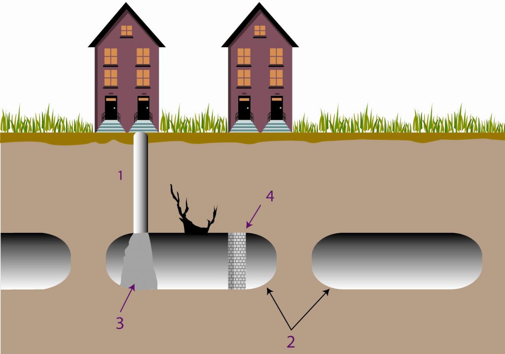
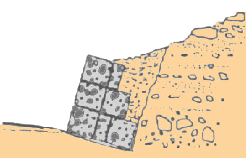
– by arranging additional pillars, by the construction of new pillars in masonry in the accessible cavities or a grouting (mixture of concrete and additives) forming studs in the inaccessible cavities (with 1: pile; 2: natural or artificial caves; 3: grouting forming stud; 4: pillar in masonry).
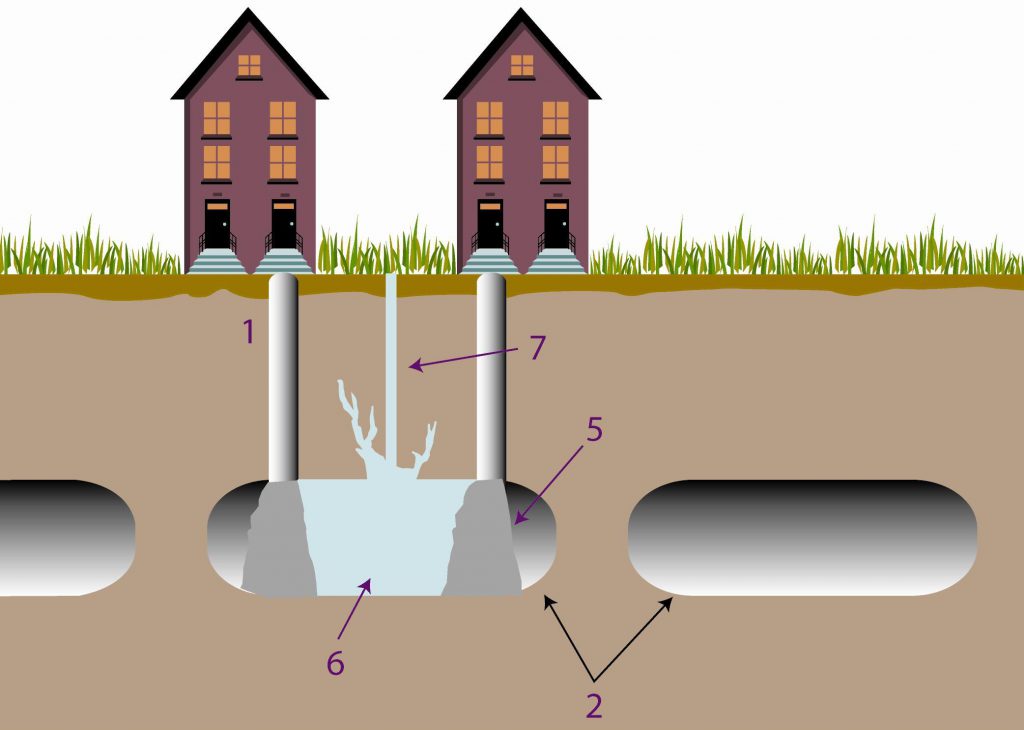
– by filling the cavity by thorough fill (if it is accessible) or by gravitating injection of liquid mortar (generally, mixture of sand, bentonite and additives) after installation of containment walls (with 1: pile; 2: natural or artificial caves; 5: liquid mortar forming containment wall; 6: filling liquid mortar; 7: injection drill).
If the cavity is close to the surface, it is essential to control the water infiltrations which could accentuate the phenomenon
B ‘passive techniques’ which seek to control the consequences of subsidence. They aim at reinforcing the structures of threatened constructions (by peripheral chaining, etc.) so that they do not undergo the consequences of the relative settlements. The realization of deep foundations, crossing the cavity, can be a means of protecting. Lastly, the buried networks must be flexible to adapt to the deformations (regular controls of their sealing must be envisaged).
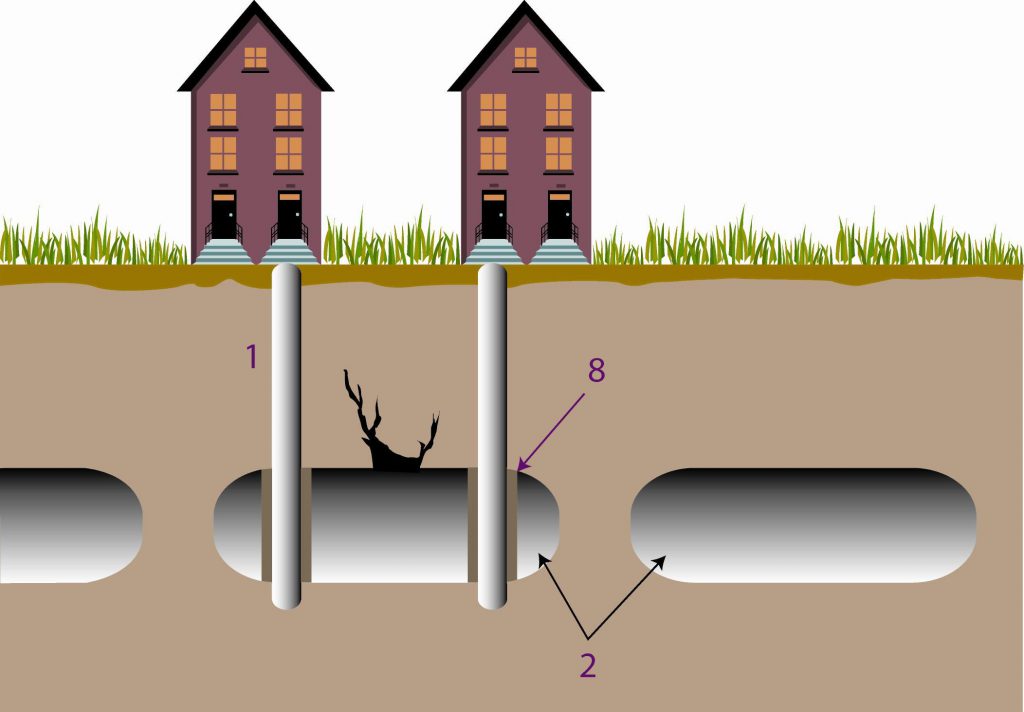
Realization of deep foundations (i.e. concrete piles), crossing the cavity, can be a means of protecting (with 1: pile; 2: natural or artificial caves; 8: casing for protection against alteration)
References
Côte, PH., fauchard, C., Pothérat, P. (2005). Méthodes géophysiques pour la localisation de cavités souterraines : potentialités et limites. In Evaluation et gestion des risques liés aux carrières souterraines abandonnées. Actes des journées scientifiques du LCPC, pp. 8-17.
Embleton, C., and Embleton C. (eds.) (1997), Geomorphological Hazards of Europe. Developments in Earth Surface Processes 5. Amsterdam : Elsevier, 524p.
Flageollet, J. C. (1988), Les mouvements de terrain et leur prévention, Paris : Masson, 224p.
LCPC (2000). Guide technique pour la caractérisation et cartographie de l’aléa dû aux mouvements de terrain. Collection ‘les risques naturels’. Laboratoire Central des Ponts et Chaussées, 91 p.
Maquaire, O., (2005). Geomorphic hazards and natural risks, In: Koster, E., A. (ed.), The Physical Geography of Western Europe, Oxford Regional Environments, Oxford University Press, Chapter 18, 354-377.
Ministère de l’Environnement, 1997, Plans de prévention des risques naturels (PPR) : guide général.. La Documentation Française, Paris, 76p.
Ministère de l’Environnement, 1999, Plans de prévention des risques naturels (PPR) : risques de mouvements de terrain. Guide méthodologique.. La Documentation Française, Paris, 71p.
Ministère de l’Ecologie et du Développement Durable, 2004. Dossier d’information sur le risque Mouvement de terrains, 20 p. (à télécharger sur site du MEDD).
Pothérat, P. (2005). L’opération de recherche « Carrières souterraines abandonnées ». Localisation, dignostic de stabilité, gestion. Rapport de synthèse. Géotechnique et risques naturels, GT 77. LCPC, 132 p.
Websites:
http://fr.wikipedia.org/wiki/Subsidence
http://www.lorraine.drire.gouv.fr/mines/g_cadreDomaine.asp?droite=2_ApresMines.asp&bas=g_MinesNavig.asp?DEST=APMINES
http://www.cgm.org/themes/soussol/mines/
http://www.cavite.net
http://www.prim.net/professionnel/documentation/dossiers_info/nat/low/mouvtTerr.pdf
http://www.catp-asso.org/cavites37/pages/missions.htm
http://clamart.cyberkata.org/