Pericolosità Naturali
Frane
Preparato da CERG – European Centre on Geomorphological Hazards (Strasbourg, France) & the Editorial Board

In generale, una frana è un movimento di una massa di roccia, terra o detrito lungo un versante, causato dall’azione della forza di gravità.
Le frane appartengono ad un insieme di processi geologici denominato MOVIMENTI DI MASSA: un movimento di massa implica il movimento verso l’esterno o verso il basso di una massa di materiale costituente il versante, determinato dall’azione della forza di gravità.
Le morfologie di frana sono distinguibili da quelle degli altri movimenti di massa grazie alla presenza di caratteristici contorni e di velocità di spostamento sensibilmente maggiori rispetto ad ogni altro movimento che interessa le porzioni di versante attigue.
Una frana è un movimento di una massa di roccia, terra o detrito lungo un versante causato dell’azione della gravità.
Le frane appartengono ad un gruppo di processi geologici denominato MOVIMENTI DI MASSA: un movimento di massa presuppone il movimento verso l’esterno o verso valle di una massa di materiale costituente il versante, in risposta all’azione della forza di gravità.
Le morfologie di frana sono distinguibili da quelle degli altri movimenti di massa grazie alla presenza di caratteristici contorni e di velocità di spostamento sensibilmente maggiori rispetto ad ogni altro movimento che interessa le porzioni di versante attigue.
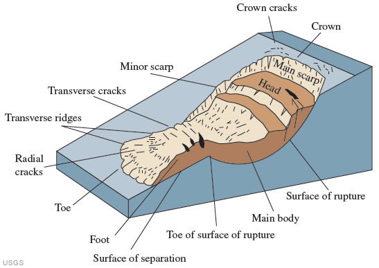
La parte sommitale è la zona di distacco (detta anche: zona di erosione, distacco o di collasso), dove il materiale che costituisce il pendio collassa e viene dislocato a valle. Il volume dislocato può rimanere in prossimità della zona di distacco o può continuare a scorrere verso valle, lungo la zona di transito, fermandosi nella zona di accumulo o fornendo materiale ad altri agenti geomorfologici (quali un fiume, il mare, un ghiacciaio ecc.). La distanza raggiunta dal materiale di frana (in Inglese “run out”) è una caratteristica specifica di ogni tipologia di frana.
I depositi di frana hanno tessiture che variano da blocchi rocciosi dislocati, ma intatti, a sedimenti altamente frammentati, che formano un deposito privo di stratificazione e scarsamente selezionato.
Le frane possono essere caratterizzate da sette stati d’attività i quali possono essere raggruppati in due categorie principali:
Attiva: la frana ha mostrato segni di attività negli ultimi 12 mesi
Inattiva: la frana non ha mostrato segni di attività negli ultimi 12 mesi.
Nel dettaglio, le frane possono essere classificate come segue:
- Attiva: la frana è attualmente in movimento.
- Sospesa: la frana si è mossa negli ultimi 12 mesi, ma attualmente non risulta attiva.
- Riattivata: la frana risulta attiva dopo un periodo di inattività.
- Quiescente: frana non attiva che può essere riattivata dalle cause originali o da altre cause.
- Abbandonata: frana inattiva che non è più soggetta alle cause che l’hanno originata.
- Stabilizzata: frana inattiva grazie a misure di mitigazione.
- Relitta: frana inattiva che si è sviluppata in condizioni climatiche o geomorfologiche molto diverse da quelle attuali. È molto improbabile che possa riattivarsi alle presenti condizioni.
There are several morphological features that can be recognized to a greater or lesser extent in most landslides. The uppermost part is the depletion or concave zone (erosional, generating or failure zone) where slope material has failed and become displaced downslope. In some cases the displacement may be only a few metres while in others the failure zone will be completely evacuated to expose the surface of rupture and to leave a distinctive scar on the hillslope.

The displaced mass may remain close to the failure zone or it may continue to travel downslope leaving a transport track ending in a colluvial accumulation zone or acting as a supply to some other geomorphic agent (e.g. river, sea or glacier). The distance that landslide material travels (runout) is a characteristic of the type of land- slide. For example, controlled by the height of fall and volume, rock avalanches can travel at high velocity for several kilometres. Runout distance and velocity for other types of landslide are controlled by factors such as volume, slope angle and morphology, clay content, water content, and surface frictional characteristics of the runout pathway.
For the references herein and for knowing sources of didactic material go to 1.3 Selected references
Case of landslide mainly governed by climatic conditions:
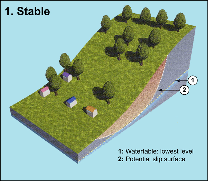
1. Slope is stable: Water table is at its lowest level. The safety factor F is > 1 (the resisting forces are superior to the driving forces).
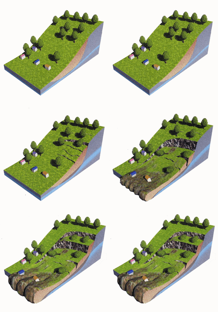
2. First failure phase: Due to the water table rises, the safety factor F is < 1. The Archimedes thrust lifts or lightens the soil. Thus, a decrease in the friction forces along the slip surface promotes movement. Rate of displacement can be more or less important. According to the climatic conditions, water table level could decrease and the slope could be “temporarily” stabilized (active or dormant!).
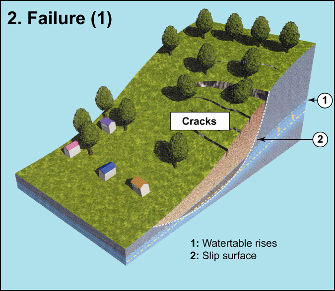
3. Second failure phase: In the event of rainy conditions, water table rises at a high level and major displacements occur. Main scarp is clearly observed. In the rear of the main scarp, on of the landslide crown, new cracks could appear.
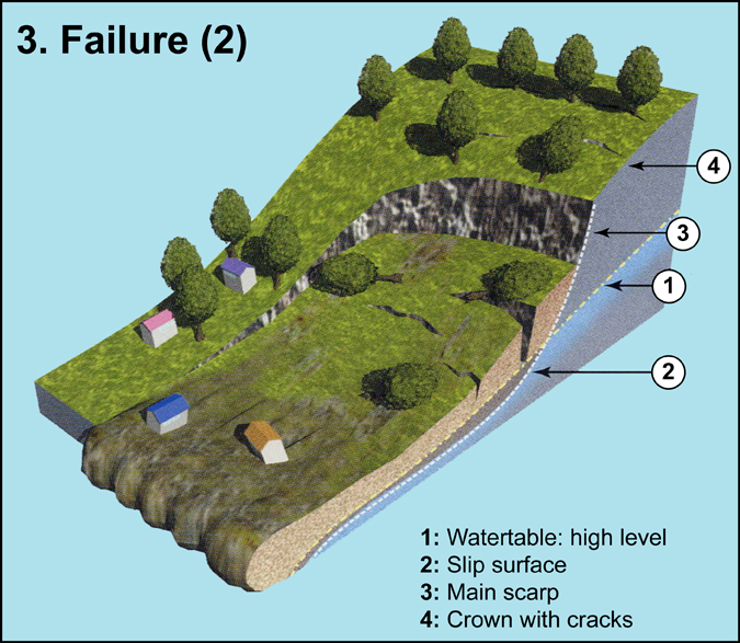
4.Reactivation: If water table rises at its highest level, reactivation along extended slip surface occurs. Secondary scarp is now well observed. According to the predisposition factors (morphological features, geological factors, land cover), water table level (or triggering threshold) which provoke the instability is different for each slope.
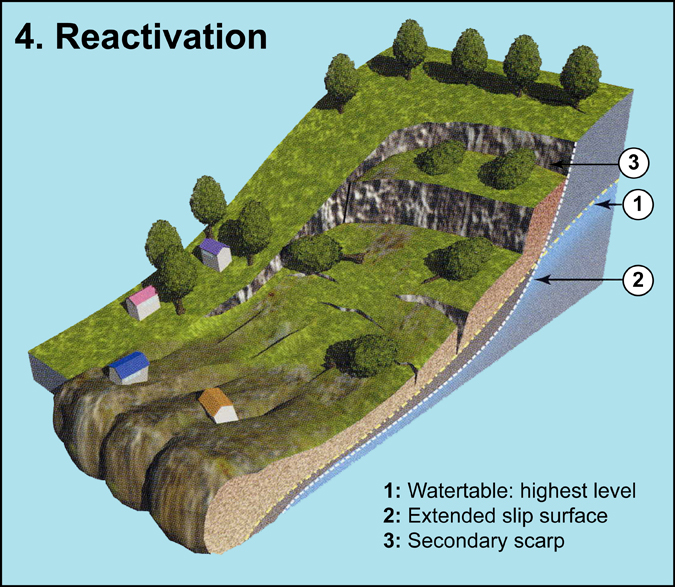
Note: delay between each phase can be very short (several days or months) or very long (several years or centuries!) – Notion of landslide activity
Landslide activity and morphological indicators:
Seven states of activity are recognized and can be classified in two categories:
- Active: landslide has moved within the last twelve months,
- Inactive: landslide has not moved within the last twelve months.
In detail, landslides can be:
- Active: landslide is currently moving,
- Suspended: landslide has moved within the last twelve months but is not active at present,
- Reactivated: landslide is active but has been inactive.
- Dormant: inactive landslide can be reactivated by its original causes or by other causes
- Abandoned: inactive landslide is no longer affected by its original causes
- Stabilised: inactive landslide has been protected from its original causes by remedial measures
- Relict: inactive landslide which developed under climatic or geomorphological conditions considerably different from those at present. It can not be reactivated.
Figure 2 shows the seven states of activity of a landslide and morphological characteristics associated (from Dikau et al., 1996):
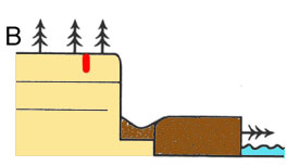
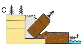
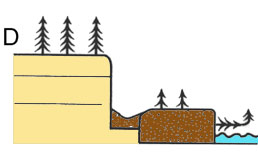
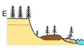
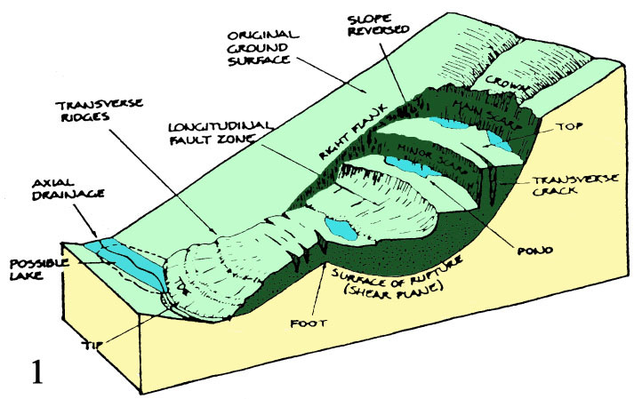
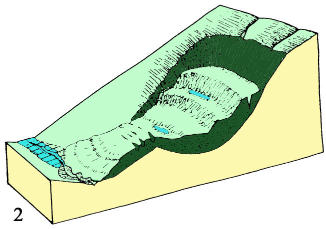
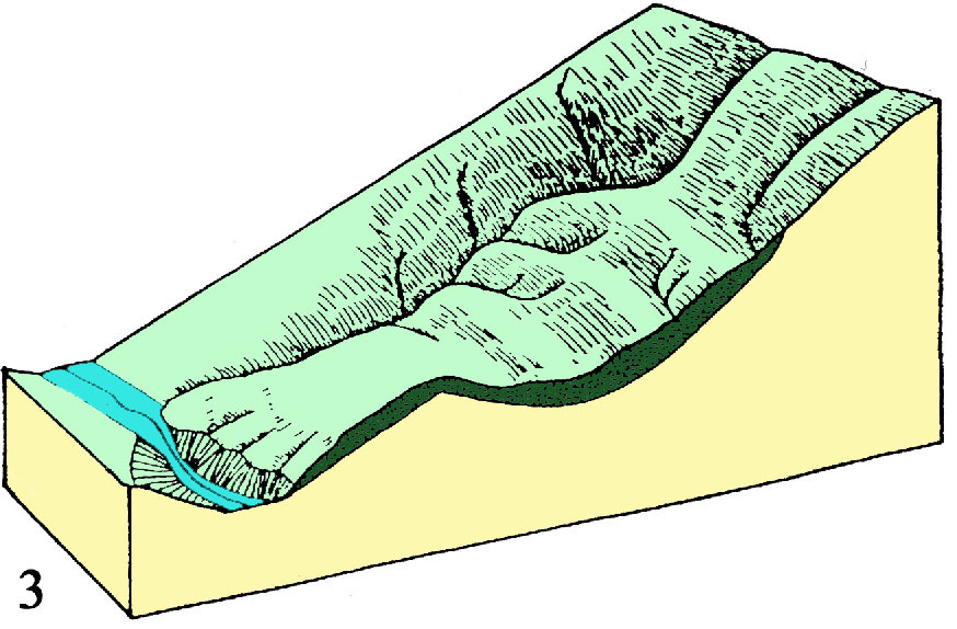
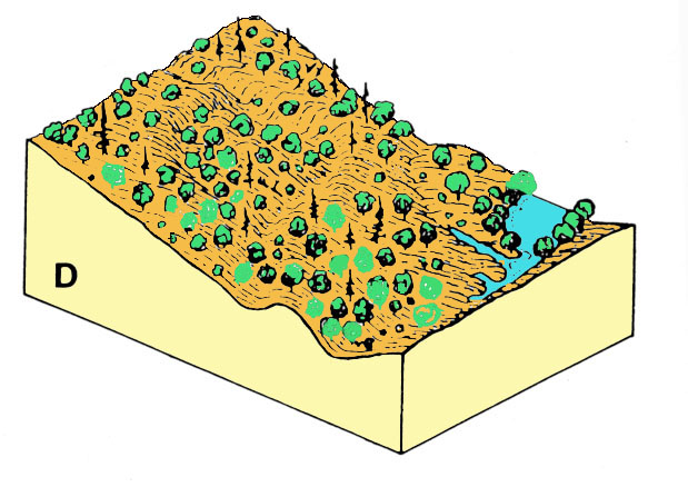
These stages can be successive in time. Figure 3 shows the block diagrams of morphological changes with time of a rotational slide, from active state to dormant state, in arid or semiarid climate (from Keaton and Degraaf, 1996). Morphological features are great indicators to assess the state of activity of a landslide:
1. Active or recently active landslide: features are sharply defined and distinct. Bedrock is freshly exposed in the main scarp or the flanks. Water is ponded in closed depressions caused by rotational movement or by blockage of original runoff paths.
2. Dormant-young landslide: features remain clear but are not sharply defined owing to slope wash and shallow mass movements on steep scarps. Although bedrock is still visible in many places, weathering has obscured the original structure. Drainage lines are not established.
3. Dormant-mature landslide: Drainage follows rifts and sags on slide mass, internal blocks are slightly dissected and material is eroded from slide mass.
4. Dormant-old landslide: features are weak and often subtle. Slide mass is almost completely removed, drainage network shows weak structural control, valley drainage re-establishes its pre-slide profile.
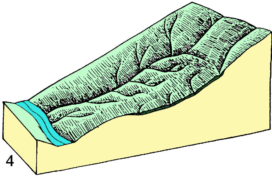
Figure 4 shows the block diagrams of morphological changes with time of a rotational slide, from active state to dormant state, in humid climate (from Keaton and Degraaf, 1996):
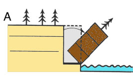
A. Active or recently active landslide: features are sharply defined and distinct. Bedrock is freshly exposed in the main scarp or the flanks. Many cracks exist above and subparallel to the main scarp; cracks extend across the slide; radial cracks occur within the toe portion. Original vegetation has been disrupted. The present orientation of vegetation indicates direction of principal movement and rotation (figure 5). Water is ponded in closed depressions caused by rotational movement or by blockage of original runoff paths.
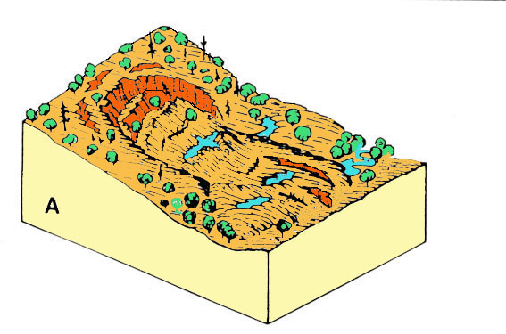
B. Dormant-young landslide: features remain clear but are not sharply defined owing to slope wash and shallow mass movements on steep scarps. Although bedrock is still visible in many places, weathering has obscured the original structure. Cracks are no longer visible within or adjacent to the slide mass. Hydrophilic vegetation has established itself in the ponded areas. Minor scarps and transverse ridges have been modified and the ground has a distinctive hummocky appearance.
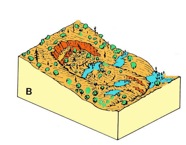
C. Dormant-mature landslide: features are modified by surface drainage, internal erosion and vegetation. Erosion has reduced the slopes of the scarp, flank and toe regions. Erosion has resulted in gullies and establishment of new drainage paths within and adjacent to the landslide. Likewise the original hummocky surface has been somewhat subdued.
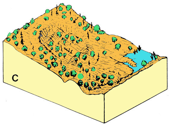
D. dormant-old landslide: features are weak and often subtle. Slope breaks are indistinguishable from scarp, flank and toe regions. Neither vegetation nor developed runoff paths reflect original landslide boundaries. The disturbed area has been completely filled with silt and heavy vegetation has disguised its location.
Use of vegetation:
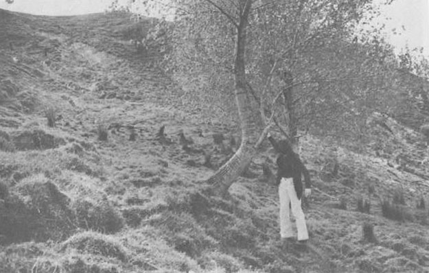
Vegetation is also used as indicator of landslide activity. It can permit to assess the degree of activity, age, type and component parts of a landslide. The term “dendrogeomorphology” (in Greek “dendro” means “tree”) is used to define the study of geomorphic processes using data gathered from trees. Tree growing on an instable slope is liable to develop a tilting or a curvature in the direction of the movement. Analysis of external deformations of the tree gives information on landslide activity.
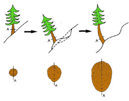
Trees that have been tilted from the vertical also undergo changes to internal tissue as they respond to the altered growing conditions. Coniferous trees support new growth by adding “compression tissue” on the lower side of the trunk, whereas deciduous trees develop “tension tissue” mainly on the upper side. Investigation of tissue disturbance in combination with analysis of the eccentricity of the tree annual rings can be used to determine dates of significant movement of the slope.
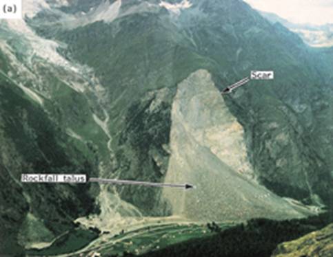
Dendrogeomorphology is used to assess slide activity, debris flow activity and also rock fall activity.
For the references herein and for knowing sources of didactic material go to 1.3 Selected references
BRAAM R.R., WEISS E.E.J., BURROUGH P.A., 1987. Spatial and temporal analysis of mass movement using dendrochronology. Catena, vol. 14, 1987b. p. 573-584
BRUNSDEN D., PRIOR D., 1984. Slope instability. John Wiley & Sons Ltd, Chichester
CROZIER M.J., 2004. Landslide in GOUDIE A.S. (Ed.), 2004. Encyclopedia of Geomorphology. Vol. 2, 605-608. Routledge, London and New York
CRUDEN, D.M. & VARNES, D.J., 1996. Landslides Types and Processes. In: A.K. TURNER & R.L. SCHUSTER (Editors), Landslides: Investigation and Mitigation. Transportation Research Board, National Academy of Sciences, Washington D.C., Special Report 247, pp. 36-75.
DIKAU R., BRUNSDEN D., SCHROTT L., IBSEN M.-L. (eds.), 1996. Landslide Recognition: Identification, Movement and Causes. John Wiley & Sons Ltd, Chichester.
FLAGEOLLET, J.-C., MALET, J.-P., MAQUAIRE, O., SCHMUTZ, M., 2004. Integrated investigations on landslides: example of the Super-Sauze earthflow. In Margottini, C. (Ed): Natural Disasters and Sustainable Development, Springer-Verlag, Berlin, Chapter 14, 213-238.
GLADE, T., ANDERSON , M., CROZIER M., J. (ed.s), 2009. Landslide hazard and natural risks. John Wiley & Sons Ltd, Chichester.
HIGHLAND L. M., BOBWROSKY P., 2008. The Landslide Handbook – A Guide to Understanding Landslides. Downloadable at USGS website. http://pubs.usgs.gov/circ/1325/
IAEG (Commission on Landslides), 1990. Suggested nomenclature for Landslides. IAEG Bull., 41: 13-16.
KEATON, J.R., DEGRAAF, J.V., 1996. Surface Observation and Geologic Mapping. In: TURNER, SCHUSTER (EDS) “Landslides : investigation and mitigation”. Transportation Research Board – National Research Council, Special Report 247, Washington, D.C., National Academy Press, pp. 178-230.
MALET, J.-P., MAQUAIRE, O.. 2004. Hydrological behaviour of earthflows developed in clay-shales: investigation, concept and modelling. In Picarelli, L. (Ed): The Occurrence and Mechanisms of Flows in Natural Slopes and Earthfills, Patron Editore, Bologna, 175-193.
MAQUAIRE, O., 2005. Geomorphic hazards and natural risks, In: Koster, E., A. (ed.), The Physical Geography of Western Europe, Oxford Regional Environments, Oxford University Press, Chapter 18, 354-377.
MAQUAIRE, O., MALET J.-P., 2006. Shallow landslidings. In BOARDMAN, J. A, POESEN, J. (Eds): Soil Erosion in Europe, Wiley, Chapter 2.8, 583-598.
PASUTO A.& SCHROTT L. – 1997. Eurolandslide. A visual journey through european mass movements. CNR – IRPI , Padova Italy. CD-ROM Windows-Macintosh
SASSA K. (ed.), 1999. Landslides of the World. Kyoto University Press, Kyoto,
TURNER A.K. & SCHUSTER R.L. (eds.),1996. Landslides: Investigation and Mitigation. Transportation Research Board, Special Report 247, National Academy Press, Washington D.C..
VALLARIO A., 1992. Frane e territorio. Liguori Editore, Napoli.
VARNES, D.J., 1978. Slope movements: types and processes. In: R.L. SCHUSTER & R.J. KRIZEK (Editors), Landslides: Analysis and Control. Transportation Research Board, National Academy of Sciences, Washington D.C., Special Report, 176, pp. 11-33.
Le forme e le dinamiche delle frane sono molto differenti e, di conseguenza, esistono molti sistemi di classificazione. I criteri generalmente utilizzati per distinguere i diversi tipi di frane sono:
- il tipo di movimento (ad esempio, crollo, ribaltamento, scivolamento, espansione laterale e colata)
- la natura del materiale coinvolto nel movimento (ad esempio, roccia, detrito, terra)
- la forma della superficie di rottura (ad esempio, curva, planare)
- il grado di smembramento del materiale dislocato
- la velocità di movimento.
L’ultimo criterio ha una grande importanza a livello pratico, giacché rappresenta una stima della probabilità che le persone hanno di evitare di essere colpite dal fenomeno dal momento in cui esso si innesca. Le velocità che i diversi tipi di frane possono manifestare sono altamente variabili:
- alcune frane mostrano movimenti di soli pochi centimetri l’anno, mantenendo questa velocità anche per decenni.
- Alcune colate di detrito hanno fatto registrare velocità di 100 km l’ora, mentre grandi valanghe di roccia sono in grado di raggiungere velocità di 350 km l’ora.
Un modo semplice di classificare le frane è combinare il tipo di movimento con la tipologia di materiale coinvolto. Questa è la classificazione basilare e comunemente utilizzata proposta da Cruden & Varnes (1996), nella sua prima edizione del 1978 dal solo Varnes, visibile nella tabella sottostante; nell’immagine seguente è rappresentato il diagramma a blocchi di Cruden & Varnes per la classificazione delle frane.

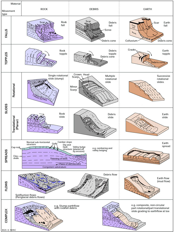
The block scheme of the Cruden & Varnes’ landslide classification. Source: British Geological Survey – www.bgs.ac.uk Go to 2.1 More information on different types of landslide)
Criteria generally used to distinguish different types of landslide include: the movement mechanism (e.g. fall, topple, slide, spread and flow), the nature of the slope material involved (rock, debris, earth), the form (curved or planar) of the surface of rupture, the degree of disruption of the displaced mass, the rate of movement. To distinguish different types of landslide we privilege here the rate of movement as it indirectly expresses the opportunity given to people to escape at the onset of the phenomenon.
Rates of movement for different types of landslide are highly variable:
- Some landslides record only a few centimetres of movement a year, sustaining this rate for decades.
- Certain debris flows have recorded velocities of 100 km/h while large rock avalanches are capable of reaching velocities of 350 km/h.

To keep things simple, we distinguish two main classes:
Slow movements The deformation is progressive and may be accompanied by rupture, but in principle with no sudden acceleration: it accelerates progressively and ends up in a sudden rupture after a phase of warning signs (cracks, deformations, subsidence), being not a direct threat if adequately monitored and controlled.
Go to 2.1.1 More details on slow movements.
Rapid movements
Movements may accelerate suddenly and they can be subdivided into two groups, depending on whether the material is propagated as a mass or reworked. These movements are more difficult to monitor and control and are consequently a major threat to personal safety.
Go to 2.1.2 More details on rapid movements
To be complete, at these two classes, we could add a third class which corresponding a spread. These are movements characterised by lateral spreading, typical of a jointed rock mass and often combined with subsidence occurring in softer, less competent underlying materials; sometimes it is not possible to recognise a basal slip surface nor well defined ductile deformation zones. Generally, the rock lateral spreading is a very slow movement but it can be very fast in the soil (debris) material: soil (debris)lateral spreading;
Go to 2.1.3 More details on lateral spreading
Another criterion used by the researchers in the identification of the landslide categories is the type of movement, whereas a further subdivision is made on the basis of the type of material.
Go to 2.1.4More information on classification
Slow movements may be distinguished by the following:
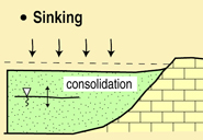
Sinking
Sinking is the process of soil consolidation under load. It affects compressible soils (peats, clays, etc). Sinking is a differential process and can cause damage to structures and buildings. Sinking is like a limited progressive subsidence.
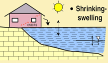
Shrinking and swelling
Shrinking is a process caused by the desiccation of the soils due to intense and/or long periods of dryness. Shrinking produces slow, low amplitude, vertical deformations of the ground surface. Shrinking can be followed by progressive swelling processes when soil humidity is increased in the wet seasons. Clayey soils are particularly sensitive to shrinking and swelling because of the specific properties of clay minerals. Shrinking can damage buildings by partial and irregular sinking of the ground.
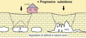
Progressive subsidence
Progressive subsidence is the process of slow surface deformation with or without fractures due to the evolution of natural or artificial caves (subterranean quarry or mines -iron, salt, coal, etc.-), circular or oval cavities or depressions appeared in surface. Go to 2.1.1.1 More information on progressive subsidence
Slide and Mudslide (or slump-earthflow):
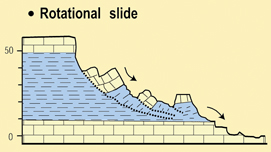
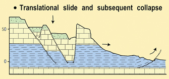
The movement takes place by means of a shear displacement along one or more surfaces or along thin zones of intense shear strain. Either rotational slides (slumps), in which the movement occurs along a curved and concave failure surface, or translational slides, in which the mass moves along a plane or undulating surface, can be found. Go to 2.1.1.2 More information on slide
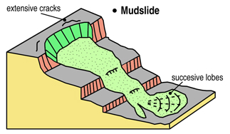
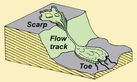
In some cases, a slide can change into a mudslide or slump-earthflow, especially on steep slopes, in highly tectonized clays or silty formations (Picarelli, 2001; Maquaire et al., 2003). As shown in figure 13, three morphological units can be distinguished: a primary source area with the main scarp and cracks, a track zone thinly covered by a flow (the paleotopography is still clearly discernible), and an accumulation zone, sometimes with several successive lobes. Go to 2.1.1.2 More information on slide>> << Return to More information on different types of landslide
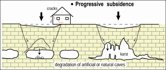
Progressive subsidence is the process of slow surface deformation with or without fractures due to the evolution of natural or artificial caves (subterranean quarry or mines -iron, salt, coal, etc.-), circular or oval cavities or depressions appeared in surface,
What is a progressive subsidence phenomenon?
Subsidence, like sinking, is a very slow process of vertical deformation of large extent. The deformations are triggered by:
- The natural dissolution of soluble materials (karst phenomena),
- The extraction of materials (calcareous, etc.) or extraction of ores (iron, salt, coal, etc.).
Subsidence is a phenomenon relatively slow which can last of many years. It generally occurs in ground terrains with flexible behaviour, or in the case of artificial cavities (subterranean quarry or mines), when the depth of exploitation is important compared to the thickness of the size. Subsidence can be the precursor sign of an evolution by rapid subsidence. Subsidence (with vertical component of the movement) results in low depth of vast topographic depressions, generating relative deformations prejudicial to the structures, or, on a large scale, a disorganization of the system of drainage. In limit of these depressions (called sink hole in case of a karst dissolution), zones in extension (with shearing and traction, yielding stresses) can lead to the appearance of cracks.
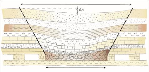
Scheme of the progressive subsidence process above a subterranean quarry by slow and progressive deformation of the ground terrain with flexible behaviour. With these indications: below, the extension of the subsidence zone, and. above, the extension of the influenced zone (from BRGM, website BDcavité.net, developed by BRGM).
References:
COTE, PH., FAUCHARD, C., POTHERAT, P. (2005). Méthodes géophysiques pour la localisation de cavités souterraines : potentialités et limites. In Evaluation et gestion es risques liés aux carrières souterraines abandonnées. Actes des journées scientifiques du LCPC, pp. 8-17.
EMBLETON, C., AND EMBLETON C. (EDS.) (1997), Geomorphological Hazards of Europe. Developments in Earth Surface Processes 5. Amsterdam : Elsevier, 524p.
FLAGEOLLET, J. C. (1988), Les mouvements de terrain et leur prévention, Paris : Masson, 224p. LCPC (2000). Guide technique pour la caractérisation et cartographie de l’aléa dû aux mouvements de terrain. Collection ‘les risques naturels’. Laboratoire Central des Ponts et Chaussées, 91 p.
MAQUAIRE, O., (2005). Geomorphic hazards and natural risks, In: Koster, E., A. (ed.), The Physical Geography of Western Europe, Oxford Regional Environments, Oxford University Press, Chapter 18, 354-377.
MINISTERE DE L’ENVIRONNEMENT, (1997), Plans de prévention des risques naturels (PPR) : guide général.. La Documentation Française, Paris, 76p.
MINISTERE DE L’ENVIRONNEMENT, (1999), Plans de prévention des risques naturels (PPR) : risques de mouvements de terrain. Guide méthodologique.. La Documentation Française, Paris, 71p.
MINISTERE DE L’ECOLOGIE ET DU DEVELOPPEMENT DURABLE, (2004). Dossier d’information sur le risque Mouvement de terrains, 20 p. (à télécharger sur site du MEDD).
POTHERAT, P. (2005). L’opération de recherche « Carrières souterraines abandonnées ». Localisation, diagnostic de stabilité, gestion. Rapport de synthèse. Géotechnique et risques naturels, GT 77. LCPC, 132 p.
Extract from Maquaire and Malet, 2006)
A slide is a mass movement of material throughout the length of a ‘rupture’ or ‘sliding’ surface. Slide could be rotational (the sliding surface is curved) or translational (the sliding surface is more or less straight). It depends on the materials but also on the shape and length of the slope. The 1:10 ratio between depth and length is a criterion for the classification of a landslide rotational or translational. Many slides are composite and the movement takes place over the length of a sliding surface which is concave upstream and flat downstream. Many slides also occur over an irregular surface (Flageollet, 1988), and they vary considerably because of the nature and size of the materials (fragments of coherent rock, loose rock, soil) and the velocity.
Rotational slides

A single rotational slide is a ‘more or less rotational movement, about an axis that is parallel to the slope contours, involving shear displacement (sliding) along a concavely upward-curving failure surface, which is visible or may reasonably be inferred’ (Varnes, 1978). The morphology of the rotational slide is typical (Figure): upstream a main scarp with a steep slope, which is the visible part of the sliding surface, and tilted blocks (counterslopes) curtailed by scars along which slide striations are sometimes visible.
Figure 1: Typical block diagram of a rotational slide (from Dikau et al., 1996)


They may be single, multiple, with several movements of the same type close to each other, or successive, i.e. interlocking (Figure). Rotational slides can vary from terracettes with an area of only a few square meters (in this case, they are considered as shallow landslides) to large slides of several hectares.
Translational slides

In translational slides, the material displaces along a planar or undulating surface of rupture, sliding out over the original ground surface. Translational slides often follow discontinuities more or less parallel to the slope, and are often superficial (such as contact between the rock and residual soils). Deeper, they occur along structural faults, joints, or bedding planes.


Translational slides on single discontinuities in rock masses have been called rock block slides (Figure 7g) or planar slides (Cruden and Varnes, 1996). Sometimes the surface of rupture may be formed by two discontinuities that cause the contained rock mass to displace down the line of intersection of the discontinuities, forming a wedge slide (Figure 7h). A stepped slide may result if two or more sets of discontinuities, such as bedding surfaces and some joint sets, penetrate the rock masses (Figure 7i).This type of slide is usually very rapid. Smooth discontinuities or thin clay levels may act as a lubricant; infiltration water reduces friction, triggers excess pore pressures and provokes the sliding of one rigid block on another.


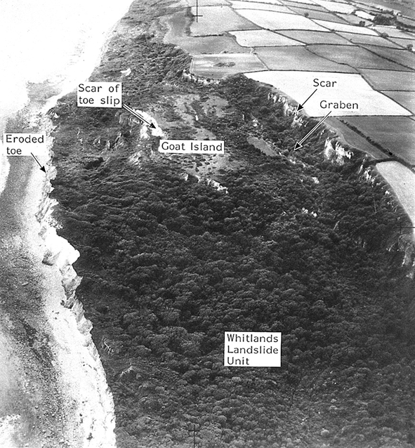
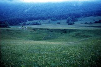
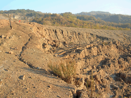
Translational slides can occur along soil-bedrock discontinuities or permeable/impermeable soil junctions in slopes formed by coherent, fine soils or coarser debris. In this case, translational slides are termed soil slides, debris slides (Figure j) or slab slides. Debris slides and slab slides are normally shallow according to their length and width. Their velocities are linked to seasonal variations in groundwater levels and in the saturated conditions.
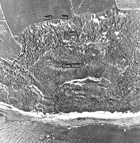
Figure 9: Oblique (on the left) and vertical (on the right) aerial photograph of the Bindon translational slide Devon, UK (from Dikau et al. 1996)
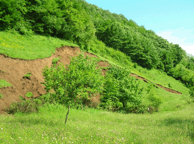
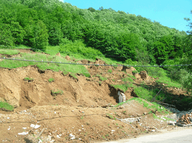
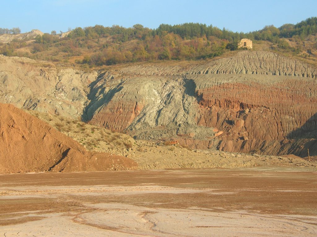
Figure 10: Translational earth slide in predominantly fine material at Deva County, Romania (photos by D. Castaldini)
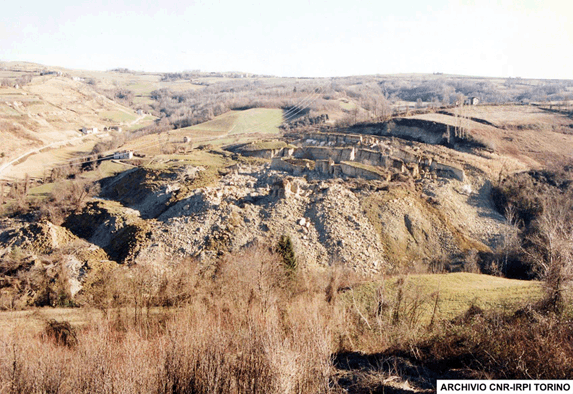
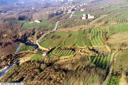
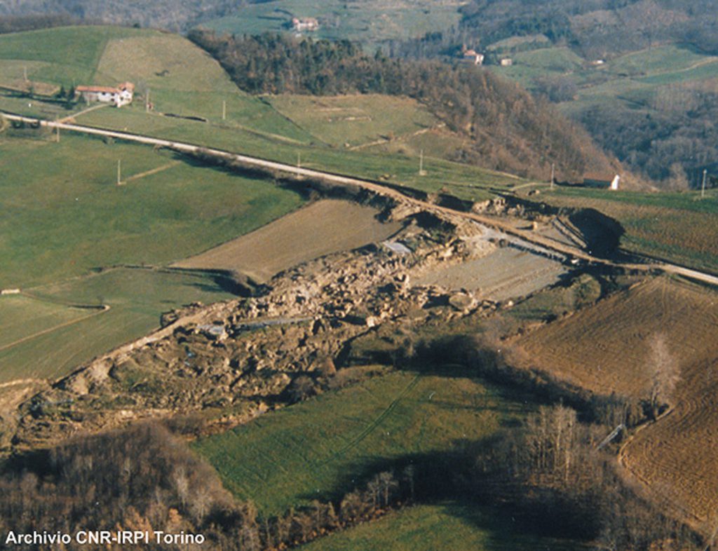
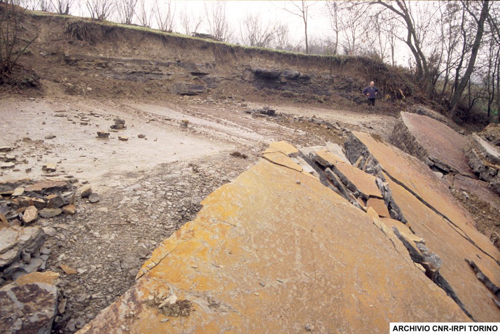
Figure 11: Translational rock slides occurred in November 1994 in Piemonte Apennines, Italy (Photos Archivio CNR IRPI, Torino)


In some cases, a slide can change into a mudslide or slump-earthflow, especially on steep slopes, in highly tectonized clays or silty formations (Picarelli, 2001; Maquaire et al., 2003). As shown in figure 13, three morphological units can be distinguished: a primary source area with the main scarp and cracks, a track zone thinly covered by a flow (the paleotopography is still clearly discernible), and an accumulation zone, sometimes with several successive lobes.
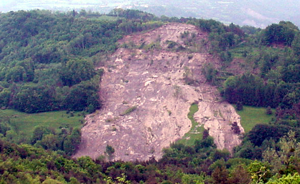
Figure 14: Mudslide triggered near the town of Corps in the Spring of 2001 (Trièves, South Alps, France, May 2001).


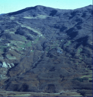

Figure 17: Boschi di Valoria earth flow, northern Apennines, Italy in 1996 (on the left) and in 2001 after its reactivation (on the rigth) (photos by A. Corsini)

References:
For the references herein and for knowing sources of didactic material go to 1.3 Selected references.
Movements may accelerate suddenly and they can be subdivided into two groups, depending on whether the material is propagated as a mass or reworked. These movements are more difficult to monitor and control and are consequently a major threat to personal safety.
Tow groups of rapid movements can be distinguished, depending on whether the materials are propagated in a mass or reworked: The first comprises:
- rapid subsidence by rapid spontaneous collapse producing sinkholes or shafts caused by the rapid rupture of natural or artificial subterranean cave vaults,
- fall: rock fall, stone fall, pebble fall, boulder fall, debris fall, soil fall arising from the mechanical development of cliffs or extensively fractured rocky escarpments,
- rockfall avalanche, topple, rockslide, of slabs from cliffs or rocky escarpments, depending on pre-existing discontinuity slabs,
Rapid subsidence
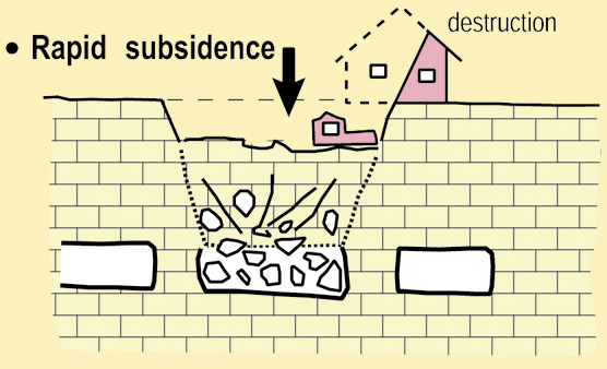
Rapid subsidence is the process of brutal spontaneous collapse producing sinkholes or shafts caused by the rapid rupture of natural or artificial subterranean cave vaults (subterranean quarry or mines -iron, salt, coal, etc.-). Go to 2.1.2.1 More information on rapid subsidence
Fall
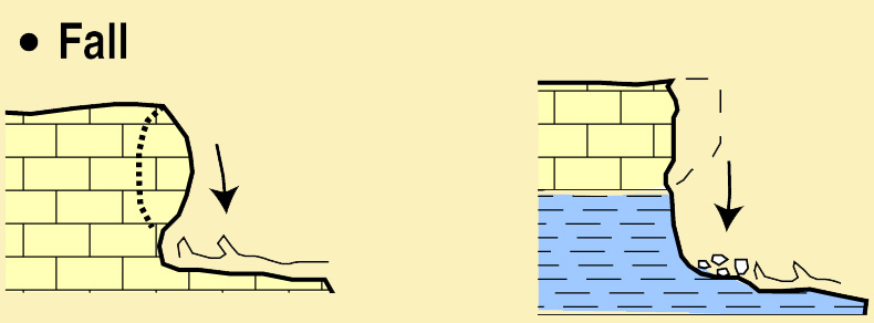
Generally the mass is detached from a very steep slope along a surface on which little or no shear displacement takes place. It occurs mainly in the air and the phenomenon includes the material’s free fall, saltation, bouncing and rolling. Go to 2.1.2.2 More information on fall>>
Rockfall avalanche
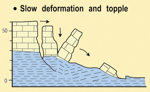
The movement is due to stresses which cause a toppling momentum around a rotation point situated below the centre of gravity of the rock mass affected. The phenomenon can evolve into either a fall (rapid movement) or slide (slow deformation).
Go to 2.1.2.4 More information on topple
The second group corresponds to the flow phenomenon. Flow is characterised by continuous movements in space fall within this class; in them the shear surfaces (or thin zones of distributed shear) are short-lived, closely spaced and not usually preserved. From the kinematic standpoint the movement could be compared to that of a viscous fluid.
This second group comprises:
- debris flow arising from the transport of material in viscous or fluid flows in mountain stream beds or on hillslopes for the debris avalanche,
- mudslide or slump-earthflow, mudflow, soil flow, generally due to the evolution of the front of landslips. Their propagation mode is somewhere between mass displacement and viscous or fluid transport.
Debris flow and debris avalanche:
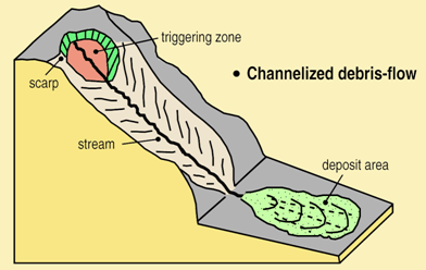
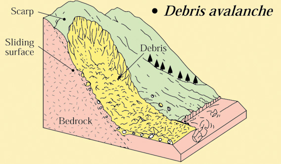
Debris flow is a very rapid to extremely rapid flow (> 1 m.s-1) of saturated non-plastic debris in a steep channel (Figure 1.m). The key characteristic of a debris flow is the presence of an established channel or regular confined path, unlike debris avalanches which are thin, partly or totally saturated, and which occur on hillslopes.
Go to 2.1.2.5. More information on flow (debris flow and debris avalanche)
Mudflow (soil flow)
Small mudflow (from Dikau et al., 1996)
Soil flows occur in wet sands or in silty-clays which are so reworked with water or so liquefied by structural collapse that they adopt a flow mode (Locat and Leroueil, 1997; Hight et al., 1998). A common term used for these conditions is mudflow. These are similar in form and behaviour to debris flows.
Go to 2.1.2.5 More information on flow (mudlow or soil flow)

Rapid subsidence is the process of brutal spontaneous collapse producing sinkholes or shafts caused by the rapid rupture of natural or artificial subterranean cave vaults (subterranean quarry or mines -iron, salt, coal, etc.-).
What is a rapid subsidence process?
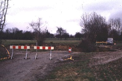
Rapid subsidence is a brutal spontaneous collapse producing sinkholes or shafts of a more or less large extent (diameter of a few meters to several hectares) and a variable depth (a few meters to many hundreds of meters). Rapid subsidence can occur after a progressive subsidence. Commonly, rapid subsidence occurs above man-made voids, such as tunnels, wells and covered subterranean quarries or mines (iron, salt, coal, etc.) It is also frequent in karst terrains, where dissolution of limestone by fluid flow in the subsurface causes the creation of voids (i.e. caves). If the roof of these voids becomes too weak, it can collapse and the overlying rock and earth will fall into the space, causing subsidence at the surface.
In uban zones, rapid subsidence can cause numerous victims. A well known disaster occurred in 1958 in Roosburg (Belgium) when 18 people were killed by a tunnel collapse of an ancient subterranean quarry. In Clamart and Issy-les-Moulineaux (France), 21 people died as an ancient subterranean quarry collapsed in 1961.
Why and how does the collapsing happen?
The Process of roof collapsing
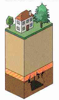
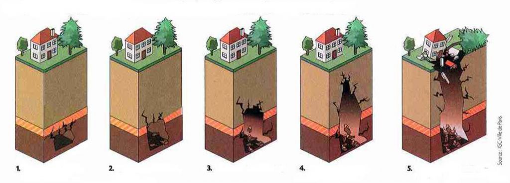
When a funnel or a shallow hole of a few meters of diameter and a few meters of depth suddenly occurs at the surface it is scientifically termed roof collapsing. Its dimensions depend on the size of the void and the nature of the bedrock which separates it from the surface.
How does this happen? For example, in the beginning there may be a gallery consisting of several vaults. These vaults may increase little by little until they finally reach the surface. Still, the roof collapsing will not occur if the gallery is sufficiently deep, because the expansion of the blocks of the roof comes to fill the void before it does not reach surface. The hazard/threat of roof collapsing is reduced if a thick and resistant bench stops progressive degradation
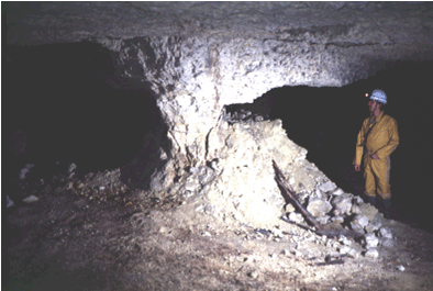
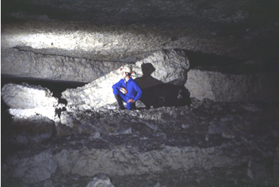
Subterranean carrier in limestone (Tours, France): progressive degradation of the pillar (diminution of its width) and roof fall (Photos: O. Maquaire, CERG).
References
Côte, PH., fauchard, C., Pothérat, P. (2005). Méthodes géophysiques pour la localisation de cavités souterraines : potentialités et limites. In Evaluation et gestion des risques liés aux carrières souterraines abandonnées. Actes des journées scientifiques du LCPC, pp. 8-17.
Embleton, C., and Embleton C. (eds.) (1997), Geomorphological Hazards of Europe. Developments in Earth Surface Processes 5. Amsterdam : Elsevier, 524p.
Flageollet, J. C. (1988), Les mouvements de terrain et leur prévention, Paris : Masson, 224p. LCPC (2000). Guide technique pour la caractérisation et cartographie de l’aléa dû aux mouvements de terrain. Collection ‘les risques naturels’.
Laboratoire Central des Ponts et Chaussées, 91 p.
Maquaire, O., (2005). Geomorphic hazards and natural risks, In: Koster, E., A. (ed.), The Physical Geography of Western Europe, Oxford Regional Environments, Oxford University Press, Chapter 18, 354-377.
Ministère de l’Environnement, 1997, Plans de prévention des risques naturels (PPR) : guide général.. La Documentation Française, Paris, 76p.
Ministère de l’Environnement, 1999, Plans de prévention des risques naturels (PPR) : risques de mouvements de terrain. Guide méthodologique.. La Documentation Française, Paris, 71p.
Ministère de l’Ecologie et du Développement Durable, 2004. Dossier d’information sur le risque Mouvement de terrains, 20 p. (à télécharger sur site du MEDD).
Pothérat, P. (2005). L’opération de recherche « Carrières souterraines abandonnées ». Localisation, dignostic de stabilité, gestion. Rapport de synthèse. Géotechnique et risques naturels, GT 77. LCPC, 132 p.
Internet Links:
http://fr.wikipedia.org/wiki/Subsidence
http://www.cgm.org/themes/soussol/mines/
http://www.prim.net/professionnel/documentation/dossiers_info/nat/low/mouvtTerr.pdf
Fall
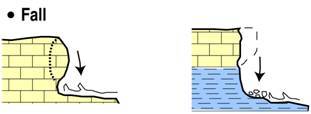
Generally the mass is detached from a very steep slope along a surface on which little or no shear displacement takes place. It occurs mainly in the air and the phenomenon includes the material’s free fall, saltation, bouncing and rolling.
What is a fall phenomenon?
(Extract from Maquaire and Malet, 2006)
Falls (and also topples) comprise a free movement of material from steep slopes or cliffs. A topple is very similar to a fall in many aspects, but normally involves a pivoting action rather than a complete separation at the base of the failure.
Their general characteristics are as follows: the shape of the rupture surface is usually smooth and vertical; the material falls suddenly from a main scarp following a preparation phase during which a slice of material is separated, damaging the intact mass; the volume and size of the fallen material are extremely variable, depending on the morpho-structural and lithological conditions of the slope. These phenomena occur on cliffs when the base is eroded by the action of the sea or of rivers. The falls are always sudden and very quick, while topples vary in speed from extremely slow to extremely quick, with acceleration and deceleration phases (Maquaire and Malet, 2006).
A fall starts with the detachment of rock or soil from a steep slope along a surface on which little or no shear displacement takes place. The trajectory of the fallen material is rectilinear and vertical for slopes with an inclination of more than 70° (Cruden et Varnes, 1996).
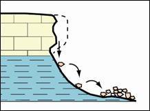
For a rock fall, material on slopes with an inclination of between 45 and 70° moves by successive rebounds, depending on the size of the material, the restitution coefficient and the angle between the slope and the trajectory of the falling mass. Throughout the length of slopes of less than 45° the falling material may roll. In the latter two cases, the material, which is very mobile, may move considerable distances from the source zone. Debris falls and soil falls are typically shallow landslides. Debris and soil falls are triggered in loose materials and their volume varies from a few cubic metres to tens of cubic metres. The accumulated material, which is not consolidated, may be easily mobilized and transported.
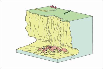
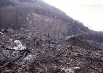
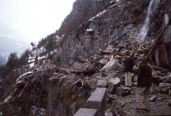
Fig. 2: Maè Valley (NE Italian Alps): January 1985 rock fall (Archivio CNR – IRPI, Padova)
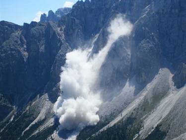
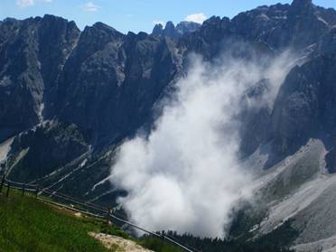
Fig. 3: Rock fall in progress at Piz Sompluf peak, Dolomites, NE italian Alps (photos Summer 2006, from Archivio Provincia di Bolzano)
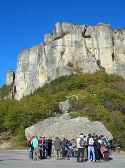
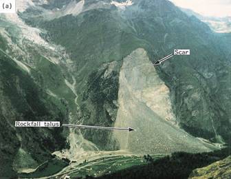
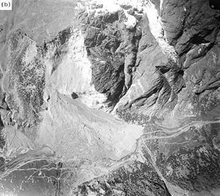
Fig. 5: Randa rockfalls, Switzerland, occurred on 18th April, 9th May 1991. The events blocked the road, rail way and river which have subsequently been diverted (from Dikau et al., 1996)
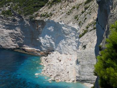
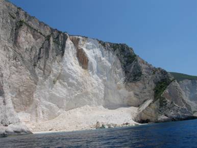
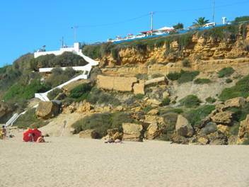
Fig. 6: Rockfall at the west coast of Zakynthos Island Greece (Photo by M. Soldati)
References:
For the references herein and for knowing sources of didactic material go to1.3 Selected references
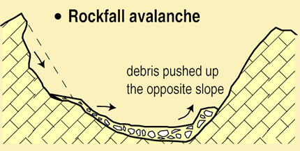
A rock avalanche is a large bulk of mostly dry rock debris deriving from the collapse of a slope or cliff and moving at a high velocity and for a long distance, even on a gentle slope.
What is a rockfall avalanche?
(Extract from Dikau et al., 1996)
A rock avalanche is a large bulk of mostly dry rock debris deriving from the collapse of a slope or cliff and moving at a high velocity and for a long distance, even on a gentle slope. Its speed can be in the order of tens of meters per second, the travel distance in the order of kilometres. In the area of accumulation, its volume can exceed 1 x 10⁶ m3, covering a total surface of over 0.1 km². Owing to its velocity and dimensions, this kind of landslide can be extremely costly in terms of human lives.
The rock avalanche can develop in two ways: first, by the fall or slide of a rock body which during movement progressively looses its cohesion by turning into dry debris and thus continues its advancement as a debris avalanche; secondly, by the sudden mobilisation of a debris avalanche, debris flow, either because of the fall of an overhanging rock mass or because of a seismic shock.
The Valpola rockfall avalanche (Italy): 28 July 1987
For the latter it is important to describe the phases that occurred on 28 July 1987 which led to be sliding of a portion of Mont Zandila in Valtellina (Italian Central Alp). At 7:25 a.m., after a preliminary phase lasting less than four days and without any sign of preceding seismic events, the detachment of a large rock volume of about 34 million cubic meters suddenly occurred. Although the collapse took place at a great velocity, its main phases of development can nevertheless be reconstructed thanks to direct witnesses and morphological evidence recorded after the event:
- The first displacements, which were relatively limited in volume, happened because of a progressive uphill widening of the crown generated by the falls occurring an hour earlier;
- After a few seconds, the entire rock mass started to slide along two main shear panes: the first was known to have 45° dip to the east, the second was a neo-formation plane dipping 35° to the north;
- Along the latter plane, the translational movements to the north, that is, toward the deep valley-floor of Valpola, took place initially with a series of short successive impulses and progressively increasing accelerations until it eventually came to a stop after the impact with a rock bluff which bordered the unstable slope. The thickness of the rock body that came into collision was estimated to be in excess of 70 m;
- Following the impact, the displaced rock, which up to that moment had remained fairly compact, was subdivided into several fragments of various dimensions, falling to the valley-floor in an easterly direction from altitudes ranging from 600 to 850 m. Therefore during this phase the gravitational event which had started as a slide, rapidly turned into rock avalanche, involving in its movement also the wood cover and the debris deposits distributed along the underlying slope. The fragmented collapsed rocks, after having obstructed a large area of the valley-floor, went up the opposite slope to a height of about 300 m, preceded by a cloud of dust which raised an altitude of 200 m.
A portion of the collapsed material fell into a previously formed barrier-lake, causing a mud wave which destroyed the village of Aquilone, located a few kilometres upstream, and claimed several lives. The volume of the accumulation deposit was estimated as 40 million m3, with a maximum thickness of 90 m. On the surface of the landslide deposit the finer fraction was composed of millimetre to decimetre fragments, while the coarser material was concentrated along the flanks of the mass movement route.
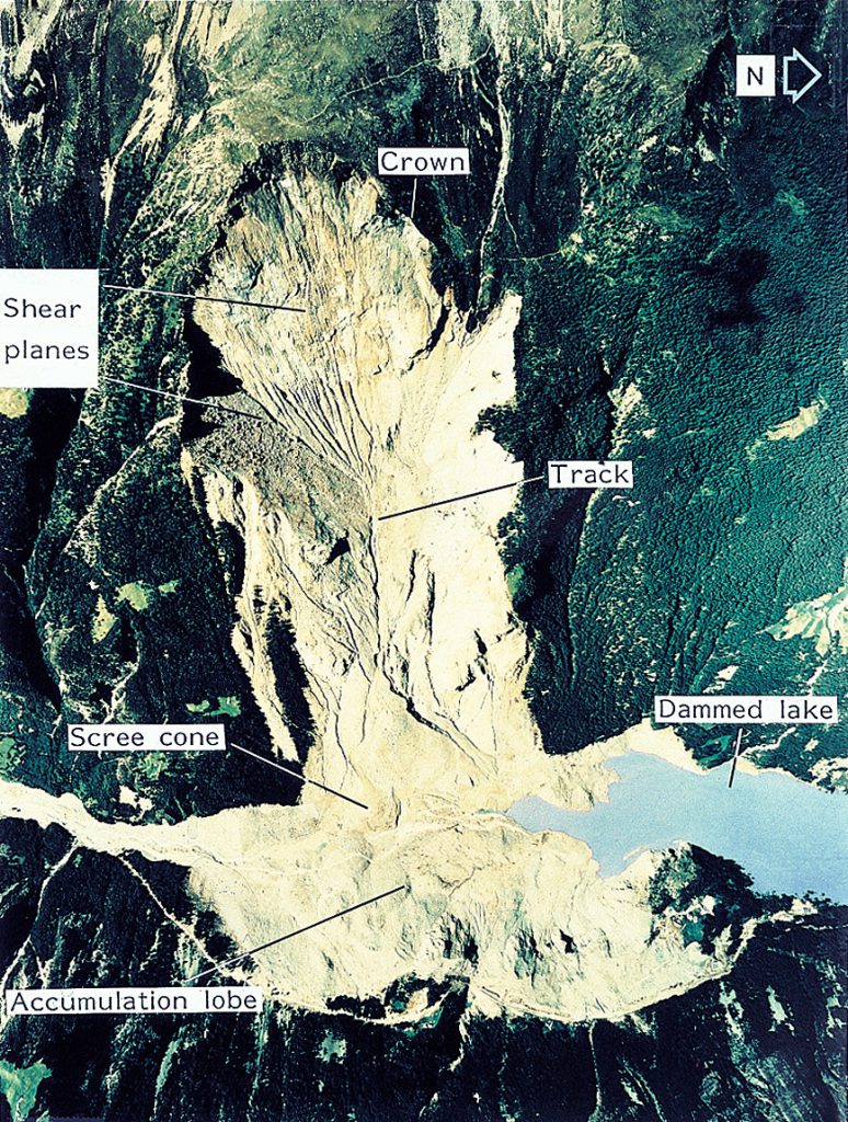
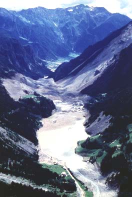
Fig. 1: The Valpola rock avalanche occurred on 28 July 1987 in the Italian Central Alps: left, aerial view to the west; right, general view to the south (from Dikau et al., 1996)
Topple:

The movement is due to stresses which cause a toppling momentum around a rotation point situated below the centre of gravity of the rock mass affected. The phenomenon can evolve into either a fall or slide.
What is a topple phenomenon?
(Extract from Maquaire and Malet, 2006)
Topples (and also falls) comprise a free movement of material from steep slopes or cliffs. A topple is very similar to a fall in many aspects, but normally involves a pivoting action rather than a complete separation at the base of the failure.
Their general characteristics are as follows: the shape of the rupture surface is usually smooth and vertical; the material falls suddenly from a main scarp following a preparation phase during which a slice of material is separated, damaging the intact mass; the volume and size of the fallen material are extremely variable, depending on the morpho-structural and lithological conditions of the slope. These phenomena occur on cliffs when the base is eroded by the action of the sea or of rivers. The falls are always sudden and very quick, while topples vary in speed from extremely slow to extremely quick, with acceleration and deceleration phases (Maquaire and Malet, 2006).

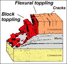
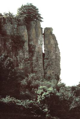
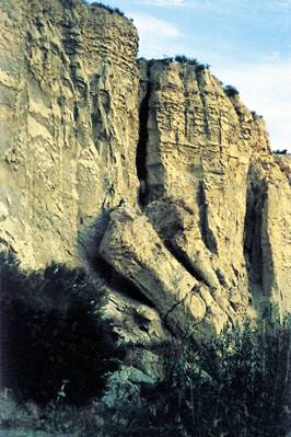
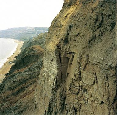
A topple is the forward rotation of a mass of rock or soil about an axis located below the centre of gravity of the displaced mass (Figure 1.c). Topples may lead to falls or slides of the displaced mass, depending on the geometry of the rupture surface and the orientation and extent of the kinematically active discontinuities. Cruden and Varnes (1996) state that the way in which topples occur may be very varied: flexural toppling occurs in rocks with one preferred discontinuity system, oriented to present a rock slope with semi-continuous cantilever beams which may develop into retrogressive complex rock topple-rock fall (Figure 1.d); block toppling occurs where the individual columns are divided by widely-spaced joints; chevron toppling occurs along complex structural configuration, where the change of dip is concentrated at the surface of rupture to give a complex rock topple-rock slide (Figure 1.e).
References:
For the references herein and for knowing sources of didactic material go to 1.3 Selected references
What is a flow phenomenon?
(Extract from Maquaire and Malet, 2006)
A flow is a landslide in which the individual particles travel separately within a moving mass. Unlike slides, occurring along more or less well-defined shear zones, flow-like landslides are characterised by internal differential movements that are distributed throughout the mass (Picarelli, 2001). Their flow-like morphologies are much longer than they are wide and their uneven topography shows successive lobes. They have a considerable erosive capacity and can carry material eroded from slopes or banks over considerable distances and cover sizeable surfaces with varying thicknesses. They contribute to positive erosion balances, as the material can be carried outside the slope basin. Coussot (1993) suggests a rheological classification of these flows. Hungr et al. (2001) distinguish several types of shallow flow-like landslides.
Debris flow and debris avalanche:
Debris flow is a very rapid to extremely rapid flow (> 1 m.s-1) of saturated non-plastic debris in a steep channel. The key characteristic of a debris flow is the presence of an established channel or regular confined path, unlike debris avalanches which are thin, partly or totally saturated, and which occur on hillslopes. Debris flows and debris avalanches are complex movements. They consist of a mixture of coarse material (gravel and boulders) embedded in a sandy-silty matrix, with a variable quantity of water (Costa and Wieczorek, 1987; Iverson et al., 1997). In spite of varying velocities and total solid fractions debris flows and debris avalanches show many similarities, particularly in the way they are triggered. Debris flows and debris avalanches are commonly triggered by an excess of water: intense rainfall, rapid snowmelt, and more rarely, glacier or lake overflows which mobilize unconsolidated material in their path. Rainfall intensity and duration, along with antecedent rainfall conditions, are strong controls for debris flow triggering (Dikau et al., 1996).
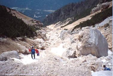
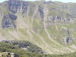
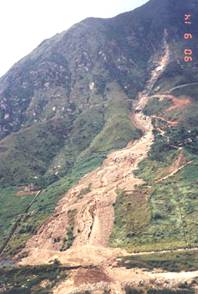
Mudflow (soil flow)

Mudflows (or Soil flows) are similar in form and behaviour to debris flows. They can be very slow to very mobile and can flow downslope quite quickly. They tend to follow gullies or shallow depressions to spread out into a flat, bulbous fan or even a thin sheet.
References:
For the references herein and for knowing sources of didactic material go to 1.3 Selected references
What is a lateral spreading phenomenon?
(Extract from Maquaire and Malet, 2006)
Lateral spreading are lateral displacements situated at a certain depth and resting on stable formations. When they occur in coherent rock, whether or not resting on clay deposits or on plastic marl, they may affect a rock massif over considerable thicknesses and are therefore considered as deep-seated landslides. For further information the reader should refer to the following: Jahn, 1964; Bentley and Smalley, 1984.
Soil (debris) lateral spreading
(from Maquaire and Malet, 2006)
We will confine our discussion to shallow lateral spreading occurring in non-cohesive heterogeneous materials such as moraine deposits (debris spreading) or fine clay or sand formations (soil spreading). Fine formations particularly sensitive to this type of movement include varved clays deposited on the banks of the great Pleistocene glaciers in Scandinavia or over smaller areas in the old pro-glacier lakes of the Swiss Alpine border or in the Alpine valleys (Trièves in France; Nieuwenhuis, 1991). Their sensitivity is due to their very low plasticity. Sands may easily liquefy and give rise to this type of movement. Lateral spreading may also develop in coarse and heterogeneous moraine formations (Noverraz et al., 2001).
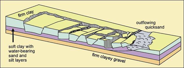
These movements may occur on very gentle slopes of 5° or less. They display a characteristic morphology (Figure): upstream at the source, a scarp with multiple lobes dominates the displaced part where horsts or rift valleys appear; downstream these shapes are elongated by perpendicular folds in the direction of the movement. The space affected by these movements is often as wide as it is long and they often occur over a very short period of time.
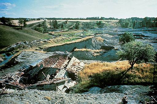
Rock lateral spreading
(From Dikau et al., 1996)
Rock spreading consists of lateral extensions of rock masses either in homogeneous rock or in cohesive rock overlying ductile materials. The latter occur along shears with tensile fractures occurring on overlying coherent rock. Though often decribed as part of complex slope movements, in certain geological conditions they give rise to such peculiar morphological features that they are considered as a separate type of movement.
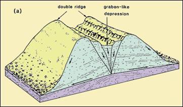
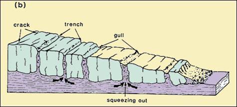
Schematic block diagram showing lateral spreading in homogeneous (a) and non-homogeneous (b) rocks (from Dikau et al. 1996)
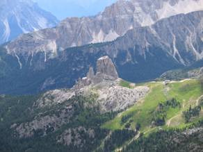
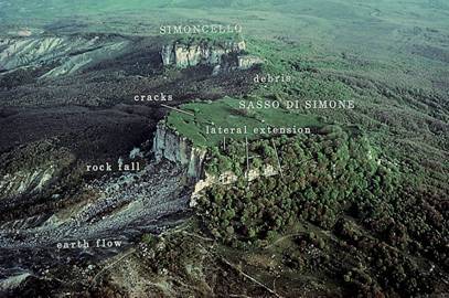
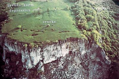
Lateral spreading at Simoncello and Sasso di Simone, northern Apennines, Italy. In the right photos a detail of cracks and trenches on the Sasso di Simone. (from Dikau et al. 1996
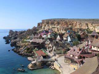
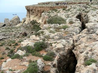
Panoramic view (left) and trench details of the lateral spreading at Popeye Village, NW coast of Malta: (photos by M. Soldati)
References:
BENTLEY SP, SMALLEY IJ.. 1984. Landslips in sensitive clays. In Slope Instability, BRUNSDEN D, PRIOR DB. (eds.). Wiley: Chichester; 457-490.
JAHN A. 1964. Slope morphological features resulting from gravitation. Zeitschrift für Geomorphologie, Supplement Band 5: 59-72.
NIEUWENHUIS JD. 1991. Variations in the stability and displacements of a shallow seasonal landslide in varved clays. Balkema: Rotterdam.
NOVERRAZ F., BONNARD C, DUPRAZ H, HUGUENIN L. 2001. Versinclim: comportement passé, présent et futur des grands versants instables en fonction de l’évolution climatique. Hochschulverlag AG: Zürich.
For the other references herein and for knowing sources of didactic material go to 1.3 Selected references.
By Alessandro Pasuto1, Mauro Soldati2, & Doriano Castaldini
21 CNR – IRPI Padova (Italy)
2 Dipartimento di Scienze della Terra, Università di Modena e Reggio Emilia (Italy)
When a study of mass movements is enterprised, which also aims to define landslide hazard, it is of paramount importance to use clear terminology which can be universally understood also by non-specialists (IAEG, 1990). It is therefore important for these phenomena to be immediately identified and subdivided according to the characteristics directly observable. In scientific literature, there are several “classifications” regarding to slope movements which have been proposed since the beginning of the 20th century. These often complied with the needs of various authors but more recently an effort has been made to use the least ambiguous terminology.
Most recent classifications try to emphasize both the processes leading to the development of a landslide and the materials involved; others are based on morphology, landslide mechanism, deformation velocity, causes of movement, geometry of the failure area and the deposits, age, etc. This section does not aim to describe the numerous “classifications” proposed but particular attention will be given to the most commonly accepted, that is illustrated and subsequently modified by Varnes (Varnes, 1978; Cruden & Varnes, 1996) Varnes proposed his first subdivision in 1958; subsequent elaborations were carried out in 1978 and 1996 and at the moment this subdivision is universally accepted.
The main criterion used by the author in the identification of the landslide categories is the type of movement, whereas a further subdivision is made on the basis of the type of material. As for the type of movement, five categories are represented: falls, topples, slides, spreads and flows. On the other hand, the materials are divided into two types: rock and engineering soil; the latter is further subdivided into debris and earth. In this way a landslide can be described by means of two words: the first one describing the material and the second one the type of movement (Table 1).

Complex: is the result of the combination of two or more of the five classes above illustrated. In the Cruden & Varnes (1996) classification the term «complex» has been retained as a description of the style of activity of a landslide. Moreover, other attributes are introduced so that the definition becomes more elaborate but more information is thus available on the gravitational movement. The type of landslide is described by a series of adjectives placed in sequence which provide information about the activity, the rate of movement, the moisture content, the material and type of movement (e.g. active rapid wet rock slide).
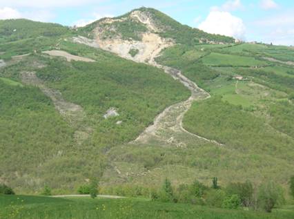
For the references herein and for knowing sources of didactic material go to 1.3 Selected references.
Le frane sono il risultato della dislocazione di masse di terreno reso instabile a seguito di:
- Fattori condizionanti
- Morfologie del terreno: geometria del versante (ovvero, altezza, lunghezza, forma, inclinazione, esposizione)
- Fattori geologici: litologia (ovvero, argilla, calcare, rocce tenere, rocce alterate), struttura e discontinuità (ovvero, stratificazione, piani di scistosità e foliazione, faglie, fratture)
- Copertura del suolo: ad esempio bosco, prato, pascolo, terreno arabile, seminativo permanente, roccia.
- Fattori scatenanti
- Processi fisici: tra cui i terremoti, le eruzioni vulcaniche, le condizioni climatiche (piogge molto intense, fusione del manto nevoso, cicli di gelo e disgelo)
- Processi geomorfologici: tra cui l’erosione fluviale o marina al piede del versante, la sedimentazione, il sovraccarico
- Processi antropici: tra cui il terrazzamento, la vibrazione, la deforestazione, lo sfruttamento di materie prime o delle falde, le escavazioni, la costruzione di strade, le attività di cava e di miniera, l’imposizione di carichi.
Le cause delle frane sono, pertanto, molteplici, agenti contemporaneamente o in sequenza temporale.
Le cause vengono spesso anche suddivise in due grandi categorie:
- Cause interne, relative alle forze resistenti.
- Portano al collasso del pendio senza che vi siano cambiamenti percettibili in superficie; sono infatti cause che riducono la resistenza al taglio del materiale. Le cause interne che condizionano la stabilità di un versante sono i fattori geologici, gli elementi geomorfologici e le condizioni climatiche.
- Cause esterne, relative a forze destabilizzanti (ad esempio, la gravità, flussi d’acqua interstiziali, pressione).
- Determinano un incremento degli sforzi di taglio attraverso più o meno evidenti modificazioni della morfologia del versante. Tra questi processi, i seguenti sono particolarmente importanti: erosione al piede operata da un corso d’acqua o dalle opere di costruzione di una strada, operazioni di miniera o di cava, sovraccarico del versante, asportazione di un supporto laterale, pressione laterale, attività tettonica, effetto della vegetazione.
Un pendio è stabile quando le forze resistenti sono maggiori o uguali alle forze destabilizzanti. Il rapporto tra le due forze viene chiamato Fattore di Sicurezza. È convenzionalmente assunto come misura del livello di stabilità del pendio.
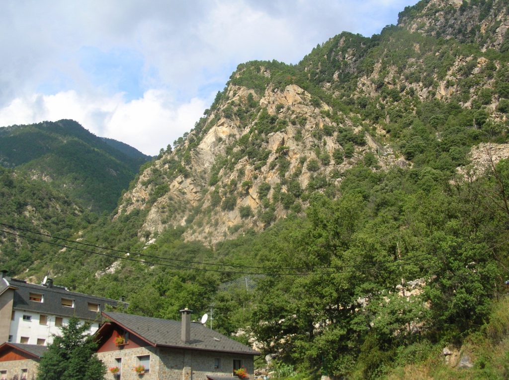
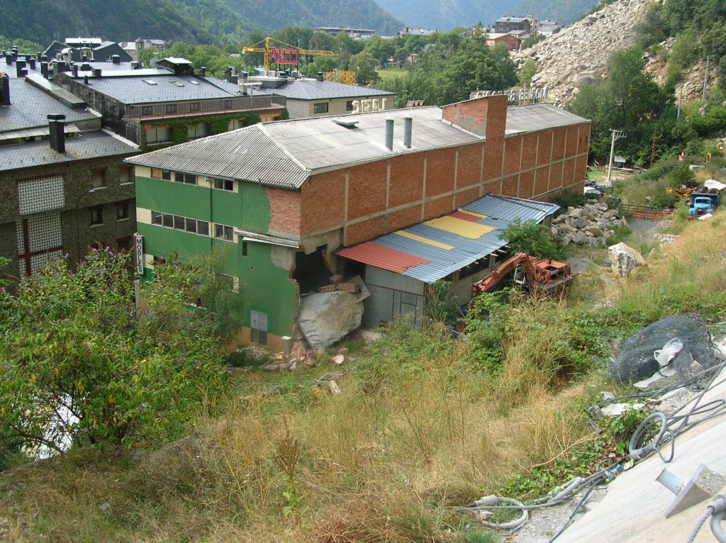
Immagine 2: Il 20 aprile 2008, in occasione di un evento meteorico molto intenso, un volume di roccia si è staccato da un versante (foto sopra) generando centinaia di frammenti rocciosi. I due blocchi più grandi oltrepassarono la staccionata presente alla base del versante ed uno dei due impattò un magazzino. (Foto di D. Castaldini, 2008).
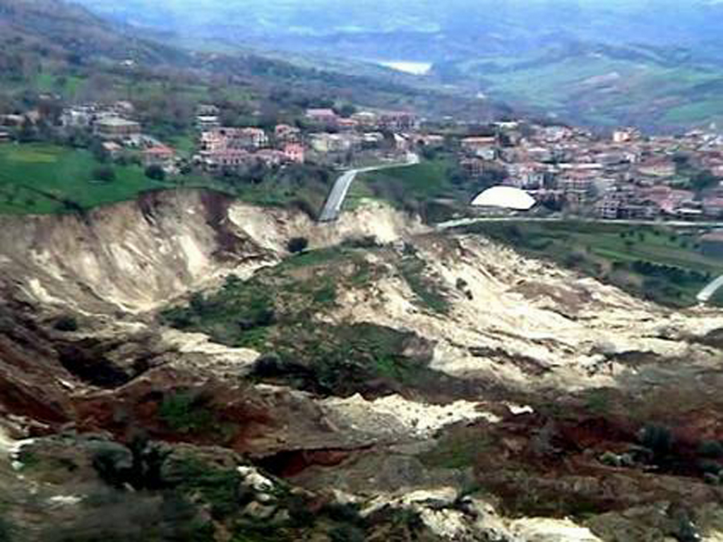
Immagine 3: Fig. 1. La frana vicina al paese di Maierato (Regione Calabria, Italia meridionale), che si verificò il 15 febbraio 2010 a seguito di abbondanti precipitazioni. Non si sono avute perdite umane e nemmeno feriti, ma circa 2300 residenti del paese furono fatti evacuare quando una porzione del versante si è staccata seppellendo le loro case sotto macerie e detriti. Anche senza vittime e feriti, i soccorritori la descrissero come una “apocalittica” devastazione e dissero che Maierato era stata ridotta ad un “paese fantasma”. Un video della frana mostra il versante muoversi lentamente (video visualizzabile al seguente indirizzo: http://daveslandslideblog.blogspot.com/2010/02/watch-this-extraordinary-landslide.html)
Landslides are associated with a displacement of masses of destabilized earth due to:
- Conditioning factors
- Morphological features: slope geometry (i.e., its height, length, shape, slope angle and aspect),
- Geological factors: nature of the soil parent materials or lithology (i.e. clay, limestone, weak material, weathered material etc.) and structure and discontinuities (bedding planes, schistosity and foliation planes, faults, fractures etc.), Landcover: forest, natural grasslands, pastures, arable lands, permanent crops, bare rocks, etc.
- Triggering factors:
- Physical processes: earthquakes, volcanic eruptions, climatic conditions (abnormally heavy rainfalls, snow melt, freeze and thaw etc.),
- Geomorphologic processes: fluvial or wave erosion at the toe of the slope, deposition, loading etc.
- Man-made processes: terracing, vibration, deforestation, the exploitation of materials or water tables, excavation, road construction, mining and quarrying, loading etc.
The causes of landslides are thus generally multiple, a conjunction or superimposition of several factors.
Causes are also often divided into two large categories:
- Internal causes, which are related to resisting forces.
- They lead to the failure of the slope without the intervention of perceptible changes on the surface; they are in fact causes which reduce the material’s shear strength. The internal causes which condition the instability of a slope are geological factors, morphological features and climatic conditions.
- External causes, which are related to driving forces (e.g. gravity, water through flow, pressure).
- They determine an increase of the shear stresses by means of more or less evident modifications of slope morphology. Among these processes the following are particularly important: Undercutting due to the erosion of a watercourse or to the excavation for road construction, exploitation of quarries or open pits, overloading, removal of lateral support, lateral pressure, tectonic activity, effect of vegetation.
A slope is stable when the resisting forces are superior or equal to the driving forces (or destabilising forces). The ratio between resisting forces and driving forces is the safety Factor. It is conventionally taken as the measure for the stability of a slope.

(photo by http://www.ansa.it/)
Fig. 1. The landslide near the southern Italian town of Maierato (Calabria region) which occurred on 15th february 2010 caused by heavy rains. No deaths or injuries have been reported, but about 2300 residents of the town were forced to evacuate when a section of hillside broke off burying their homes under rubble and debris. Though there were no injuries or deaths, relief workers on the scene described ”apocalyptic” devastation and said that Maierato had been reduced to a ”ghost town”. A video of the landslide shows the hillside slowly moving forward (e.g. see video at: http://daveslandslideblog.blogspot.com/2010/02/watch-this-extraordinary-landslide.html)
The role of water is significant but very varied. In the first instance it acts on the state or consistency of materials, for example, for clay and for an increase in water holding capacity, passage from a solid to a plastic and then to a liquid state. Secondly, the water transports material. Finally and most important, it acts on the underground water by means of the Archimedes thrust (Terzaghi’s law) which lifts or lightens the soil (Terzaghi, 1950). In the soil, the “Archimede thrust” is characterized by a decrease of effective normal stress (transmitted by the solid soil skeleton). The soil is lightened and the bulk unit weight is like: g – gw = g’
The consequence for the slopes is a decrease in the friction forces along the surfaces of the rupture, which promotes movement. Everyone can observe this phenomenon in the bath or in the swimming pool!

Effective normal stress (s’) Due to the decrease of the effective normal stress at the surface of the bathroom with the body, the man could easily move and fall down in the water!! The role of water may be appreciated by studying previous climatic conditions, both close and distant, which will contribute to feeding the water table (see case study: Villerville-Cricqueboeuf landslide IS MISSING).
By Alessandro Pasuto1, Mauro Soldati2, & Doriano Castaldini2
1 CNR – IRPI Padova (Italy)
2 Dipartimento di Scienze della Terra, Università di Modena e Reggio Emilia (Italy)
As regards the causes of mass movements, they can be divided into two large categories:
- internal causes: they lead to the failure of the slope without the intervention of perceptible changes on the surface; they are in fact causes which reduce the material’s shear strength;
- external causes: they determine an increase of the shear stresses by means of more or less evident modifications of slope morphology.
Naturally, the factors belonging to these two categories can be combined to varying extents so they do not fit in with any particular classification.
Let us now consider more in detail the internal causes which condition the stability of a slope.
- Geological factors.
- Morphological features.
- Climatic conditions.
As regards external causes which result in an increase of shear stresses, those processes giving rise to changes in slope geometry, mainly with an increase of the gradient, should first be considered. Among these processes the following are particularly important:
- Undercutting due to the erosion of a watercourse or to the excavation for road construction,
- Exploitation of quarries or open pits
- Overloading
- emoval of lateral support
- Lateral pressure
- Tectonic activity
- Effect of vegetation
External causes are related to driving forces (Geometrical changes, Unloading, Loading, Shocks and vibrations). They determine an increase of the shear stresses by means of more or less evident modifications of slope morphology. Internal causes are related to resisting forces (Progressive failure, Weathering, Seepage erosion, Water regime change). They lead to the failure of the slope without the intervention of perceptible changes on the surface; they are in fact causes which reduce the material’s shear strength
Geological factors.
They are given by all the primary characteristics that make up a slope, first of all lithology which includes both the rock’s mineralogical and textural composition and its structure. Among rock types more easily subject to disarrangement phenomena, clays are to be quoted, both those of primary origin and those derived from the meteoric weathering of volcanic materials. Argillaceous soils are particularly subject to instability phenomena such as flows.
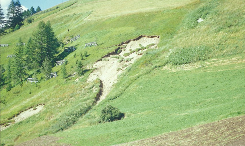
Fig. 1: Superficial earth slide (Soil slip) in weathered volcanic materials at S. Cassiano, Dolomites, E Alps, Italy (photo by M. Marchetti)
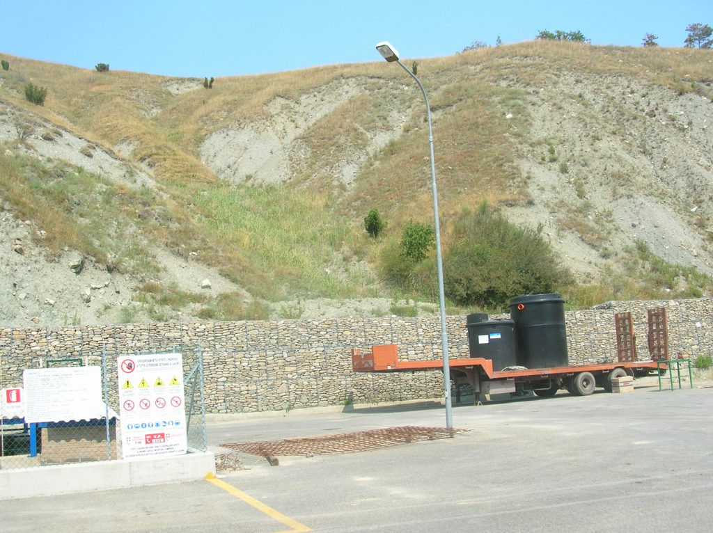
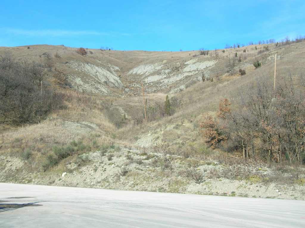
Fig. 2: Earth flows in clay materials in the Torrent Tiepido valley, Northern Apennines Italy (photos by D. Castaldini)
Also the structure of the formation involved is very important. For example, formations made up of alternating layers, such as flysch, where rock types showing ductile mechanical behaviour overlie brittle rocks, are usually subject to widespread and vast landslides. Also discontinuities, both primary (bedding planes) and secondary (schistosity and foliation planes), play an important role in the materials’ geomechanical behaviour especially with regard to mass movements such as the attitude of layers (low-angle dip-downstream beds will generally be more prone to sliding than dip-upstream levels).
Of course, all these intrinsic characteristics of the materials can undergo changes of varying intensity and rapidity during the stages of a slope’s evolution. In fact, certain kinds of processes which to some extent modify the materials’ chemico-physical characteristics can take place, causing a consequent decrease of shear strength. Among geological factors, also the tectonic history of the slope should be considered. The presence of important structural discontinuities such as faults, fractures, cleavage, joints, slickenside or even folds, fault-folds etc. induce an intrinsic weakness of the internal bonds thus making the slope particularly prone to landsliding.
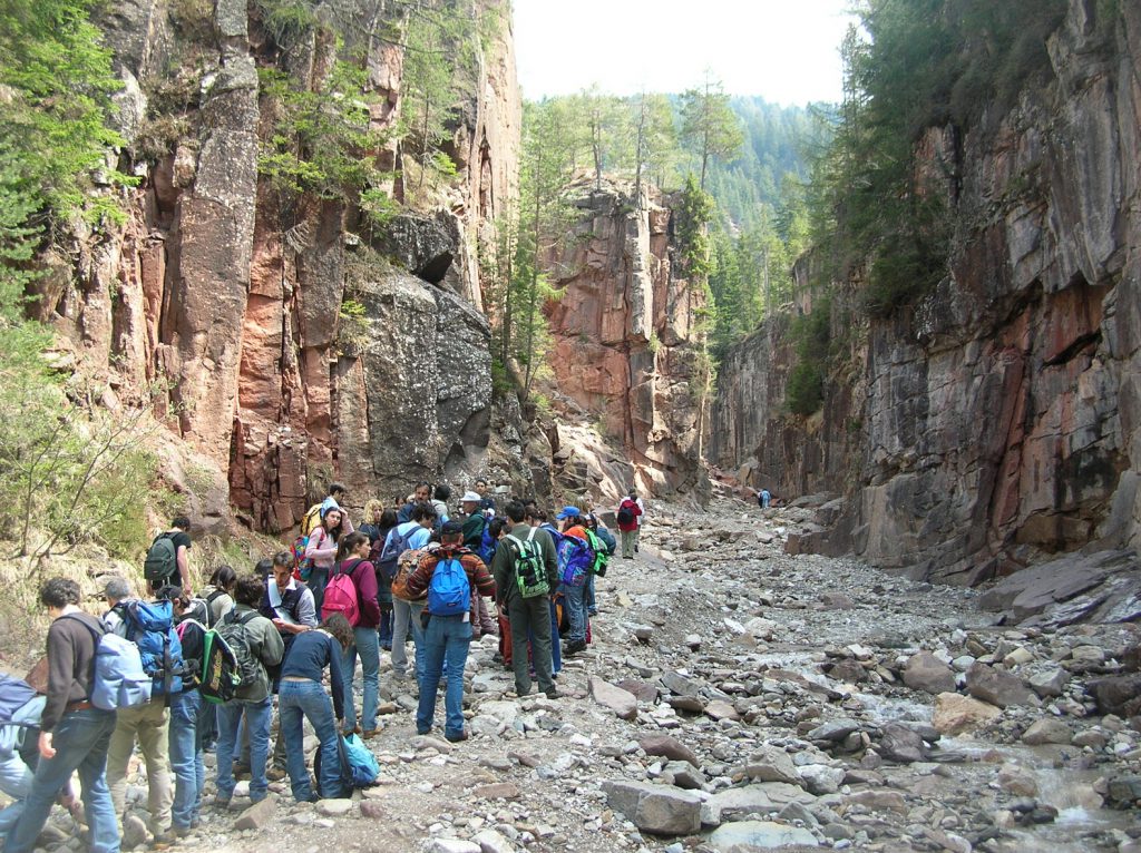
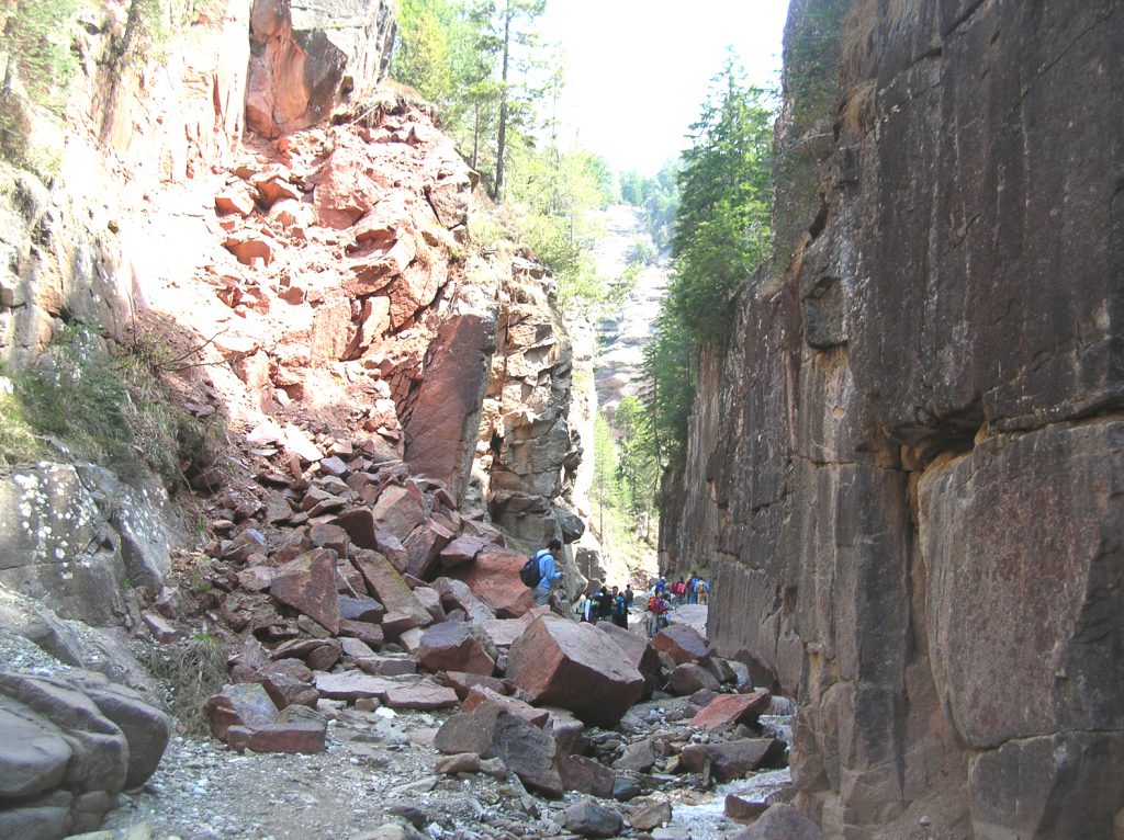
Fig. 4: Rock fall (below) in fractured volcanic formation (above) at Bletterbach Gorge, Northern Italy (photos by D. Castaldini)
Morphological features.
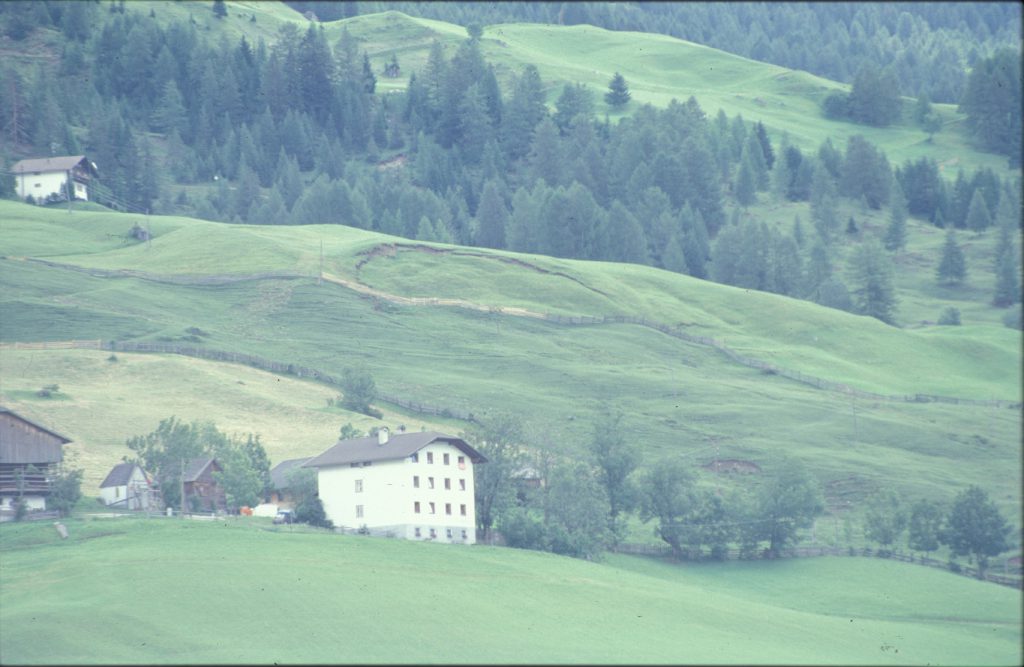
They include first of all the slope geometry, i.e. its height, length, shape, slope angle and aspect. The influence of the slope gradient is quite evident with respect to stability; indeed, very vast and steep slopes are more predisposed to disarrangement; on the other hand, even low-angle slopes can be subject to particular types of landsliding such as, for example, flows.
Climatic conditions.
Although there are several climatic parameters playing some role in the starting of landslides, the most important one is without doubt rainfall. Rainfall should be considered not only as the triggering pluviometric event (considering therefore only its intensity) but also as the amount of rain falling and accumulating during a certain period (considering also the length of time). If the percolation velocity is low, the rainfall duration assumes predominant importance for the triggering of the movement; on the contrary, in soils characterised by high hydraulic conductivity the function played by rainfall intensity becomes of paramount importance. The role of water mainly consists of an increase in porewater pressures caused by variations of the groundwater level. The cyclicity of these changes is a determining factor in weakening the internal bonds of the materials making up the slope. The influence of the various types of rainfall will of course be different according to the type of landslide. (go to 3.1.1 More details on the role of water)
Therefore, intense and time-concentrated rainfall will be particularly effective in triggering spatially limited movements such as debris flows, soil slips, mud flows, whilst prolonged precipitations could mainly give rise to slides and complex phenomena.
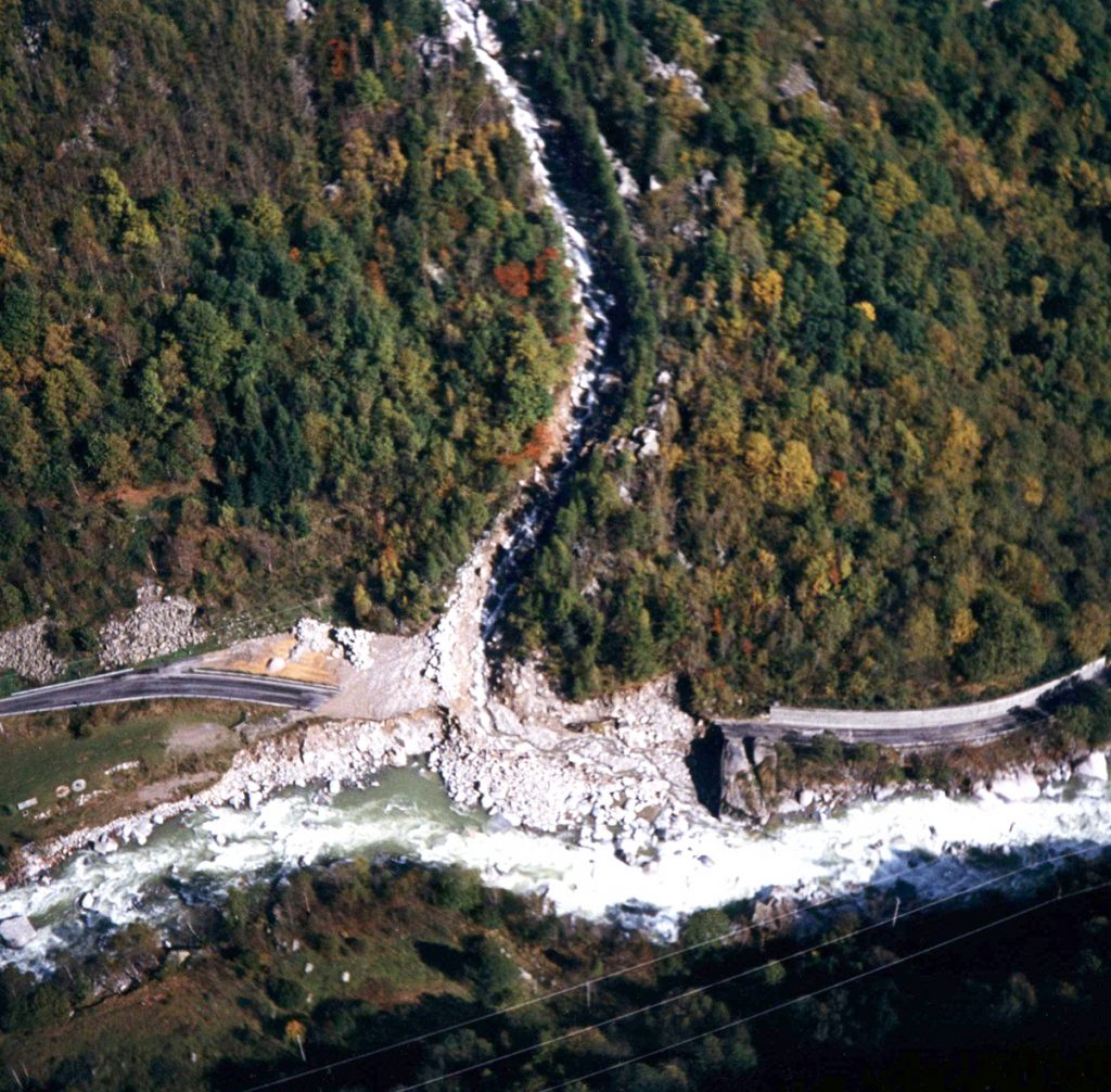
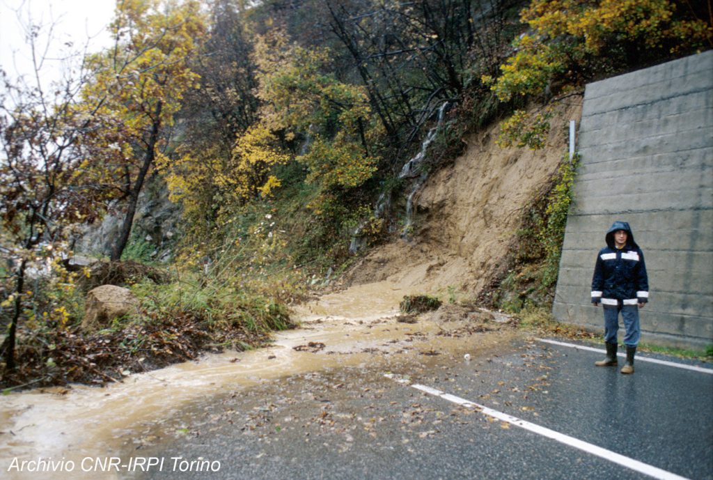
Fig. 6: Examples of debris flow and soil slip, following an intense rainy period in autumn 1994, which caused roads interruptions Piemonte Region, NW Italy) (photos by F. Luino)
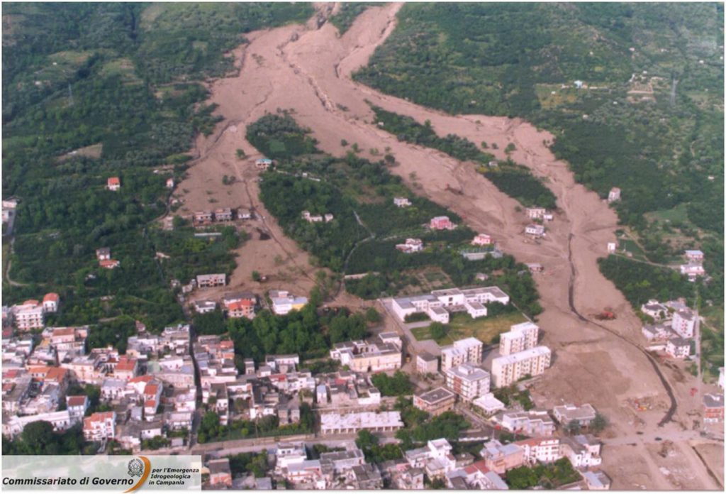
As regards external causes which result in an increase of shear stresses, those processes giving rise to changes in slope geometry, mainly with an increase of the gradient, should first be considered. Among these processes the following are particularly important:
- Undercutting due to the erosion of a watercourse or to the excavation for road construction,
- Exploitation of quarries or open pits
- Overloading
- Removal of lateral support
- Lateral pressure
- Tectonic activity
- Effect of vegetation
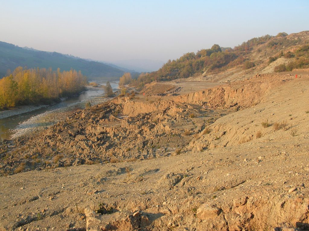
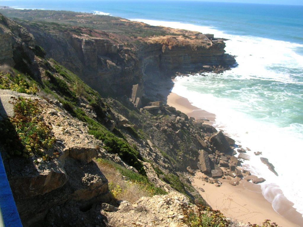
Slope geometry can change also because of phenomena taking place underground: for example, the formation of large cavities owing to mineral chemical solution or squeezing out of underlying ductile materials.
Overloading can be another phenomenon inducing an increase of applied shear stresses. This can happen owing to both natural causes, such as soil imbibition by rain or snow melt, accumulation of materials from volcanic eruptions, avalanches, debris flow or other movements, types of vegetation etc., or human activities as, for example, in embankment construction, buildings or other structures, in accumulation of tailings from mines and pits or in lacustrine basins or artificial reservoirs.
Also the removal of lateral support exerting a counterthrust on the slope could be a cause of unbalance. For example, a glacier’s withdrawal is one of the most frequent causes which determined vast post-glacial landslides in the Alps. To this category also tectonic phenomena such as activities along fault planes and subsidence should be ascribed, besides gravitational movements themselves. It is, in fact, obvious that the detachment of a portion of slope induces in the in-place material a redistribution of the stresses which can eventually cause a new movement.
Another factor which can favour the development of mass movements is lateral pressure. It can be exerted by water percolating into joints or by ice; also swellings due to hydratation could induce considerable lateral pressures as well as the mobilisation of residual tectonic stresses.
Tectonic activity can be a direct cause of slope movements in the case of regional tilting or uplift. Also in this case the effect of the tectonic process takes place essentially by means of an increase of the slope gradient. Finally, superficial deformations induced by volcanic processes can increase the shear stress within a slope also locally.
A particular discussion should be reserved for seismic shocks and other transitory stresses such as vibrations induced by operating machines, explosions, rock falls etc. These events can cause both a reduction of the materials’ shear strength and an increase, although temporary, of shear stresses. The former can be exemplified by phenomena such as liquefaction induced by sudden, cyclic increases of porewater pressures with a consequent instantaneous decline of the soil’s resistance and the collapse of the slope. This happens most frequently in saturated cohesionless medium-fine materials such as sands, silts, clays etc. The increase of shear stresses is on the contrary linked to both the accelerations to which the materials are submitted during vibrations and the temporary increment of the gradient angle in unstable slopes.
One of the first earthquake-triggered landslide was documented as early as 372-373 B.C. when Helice, a Greek city on the northern coast of the Peloponnese, slid into the sea after having been razed to the ground.
Thousands other examples occurred in historical and recent times. For instance the earthquake that occurred in Friuli (eastern Italy) on 6th May, 1976, with a main shock of magnitude 6.4 and intensity IX-X (Mercalli scale), produced numerous landslides activated; they mainly consisted of rock falls and, to a lesser extent, block-slides.
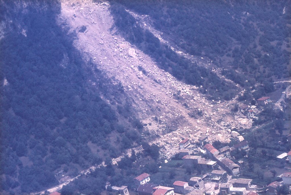
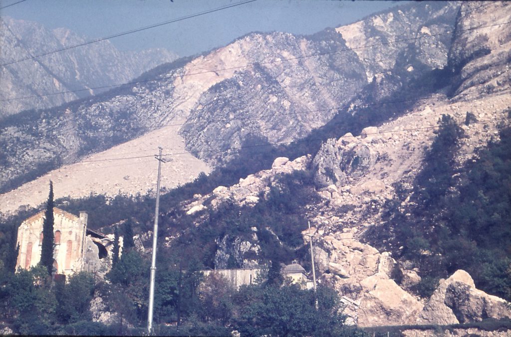
Fig. 11: Landslides induced by the earthquake which occurred in Friuli (North- Eastern Italy) on 6th May, 1976, magnitude 6.4, intensity IX-X (photos by M. Panizza)
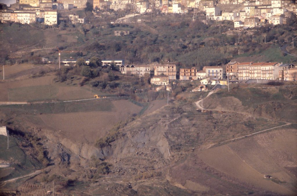
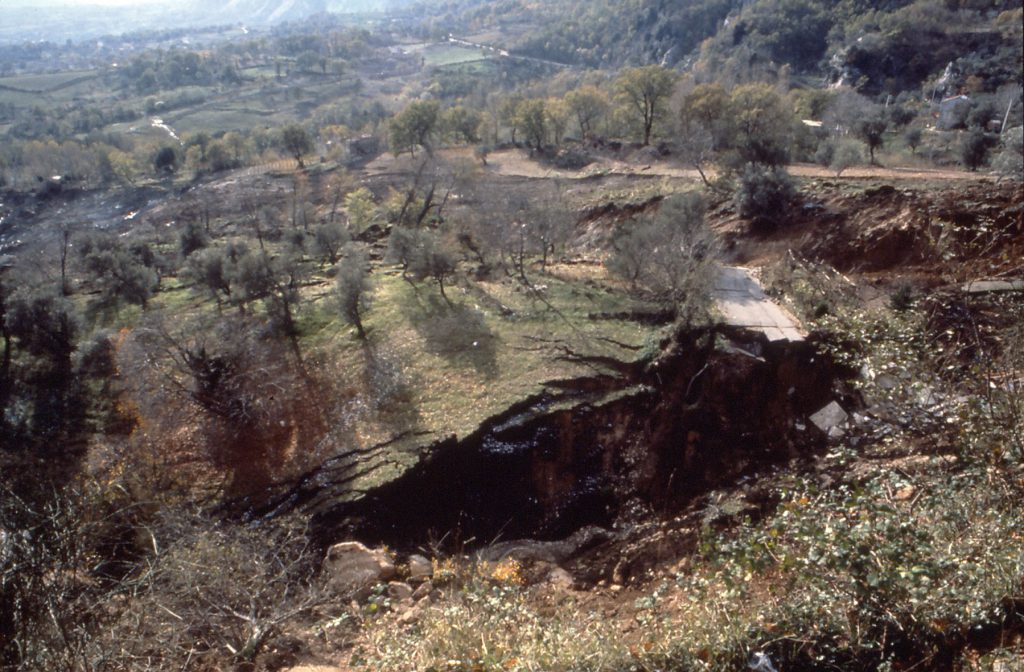
Fig. 12: Landslides induced by the earthquake which occurred in Campania and Basilicata (Southern Italy) on 23rd November 1980, magnitude 6.8, intensity X (photos by M. Panizza)
Finally, the effect of vegetation on slope stability may be twofold: sometimes it promotes stability by reducing the action of climatic agents on the slopes, protecting the soil from precipitations, wind and sunshine; it retains a considerable amount of rain water by means of leaves, branches etc. and eliminates water through evapotranspiration; runoff and erosion decrease and there is an increase in shear resistance of the slope thanks to the roots. On the other hand, the presence of vegetation may originate negative effects by increasing the load on slopes, enhancing the action of wind forces on the trees and disjointing the soil through the action of tree roots which widen cracks and favour infiltration.
References:
PASUTO S. and SOLDATI M. Landslide Hazard in PANIZZA M (1996). Environmental Geomorphology. Developments in Earth Surface Processes 4. Elsevier Science B.V., 180 -187, Amsterdam.
A slope is stable when the resisting forces are superior or equal to the driving forces (or destabilising forces). The ratio between resisting forces and driving forces is the safety factor F. It is conventionally taken as the measure for the stability of a slope. Parameters involved in calculation of the safety factor can be summarized with figure 1 (from Besson, 2005):
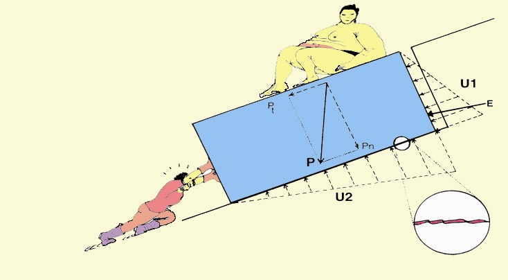
With:
Sumo is the overload
The other man is the thrust force
P: weight of material (force)
Zoom corresponds to the characteristic of the slipping contact surfaces
Resisting forces:
Pn: normal component of P
Normal component of the overload (Pn)
Normal component of the thrust force (Pn)
Driving forces (or destabilising forces):
Pt: tangential component of P
U1 and U2: hydrostatic pressure due to the “Archimedes thrust”
E: flow pressure
Tangential component of the overload (Pt)
Tangential component of the thrust force (Pt)
The safety factor is also defined as the ratio between shear stress and shear strength in a loaded mass:
F =1//0
With = available shear strength and 0 = shear stress at the speed of 0
Shear strength: cohesion and effective inter-particle friction; internal resistance of a material to shear stress. The shear strength is function of temperature, confining pressure, shape, size, loading rate and amount of pores. It is an important parameter in the determination of engineering and geomorphic properties of materials.
Shear stress: two perpendicular loads or stresses applied tangential to the surface of material, producing angular deformation in the material.
A safety factor less than or equal to1 indicates that the slope is instable. Indeed, as the shear stress approaches the maximum available shear strength, the safety factor becomes 1 and failure is imminent. If the slope is destabilized by triggering factors (earthquake, rainfall, etc.), the apparent increase of the shear stress over the available shear strength is equivalent to the acceleration of the sliding mass. Three stages can be distinguished (figure 2):
- Stable, F>1,5: the margin of stability of the slope is sufficiently high to withstand all destabilising forces;
- Marginally stable, 1,0
- Actively unstable, F~1,0: destabilising forces produce acceleration of the sliding mass (continuous or intermittent movements).
Moreover, safety factor value is time-dependent (figure 2). The movement phase is split into pre-failure, failure and post-failure stages with the possibilities of occasional reactivation. All types of movements at a given stage are associated with specific controlling variables that are subdivided into predisposition and triggering factors. Slope instability responds to a combination of these factors. The predisposition factors change most times only gradually over time whereas the triggering factors are transient. Triggering factors may either increase the shear stress, decrease the shear strength of the material or both.

References:
BESSON L., 2005. Les risques naturels: de la connaissance pratique à la gestion administrative. Editions Techni. Cités, Voiron, 60 p.
VAN ASCH T., MALET J.P., VAN BEEK L., AMITRANO D., 2007. Techniques, issues and advances in numerical modelling of landslide hazard. Bulletin de la société géologique de France, n°178, p. 265-288
Questi fenomeni si possono solitamente verificare in zone montuose o costiere, a seguito dell’instabilità dei versanti e delle falesie, ma possono anche aver luogo nelle zone pianeggianti e nei plateau, laddove si verifichino fenomeni di degradazione del suolo.
Le frane possono essere sia:
- sub-aeree (processi che hanno luogo al di sopra del piano campagna) che
- sub-acquee.
Alla fine dell’ultimo secolo si è registrato un forte incremento del numero di catastrofi naturali e, in particolare, di frane.
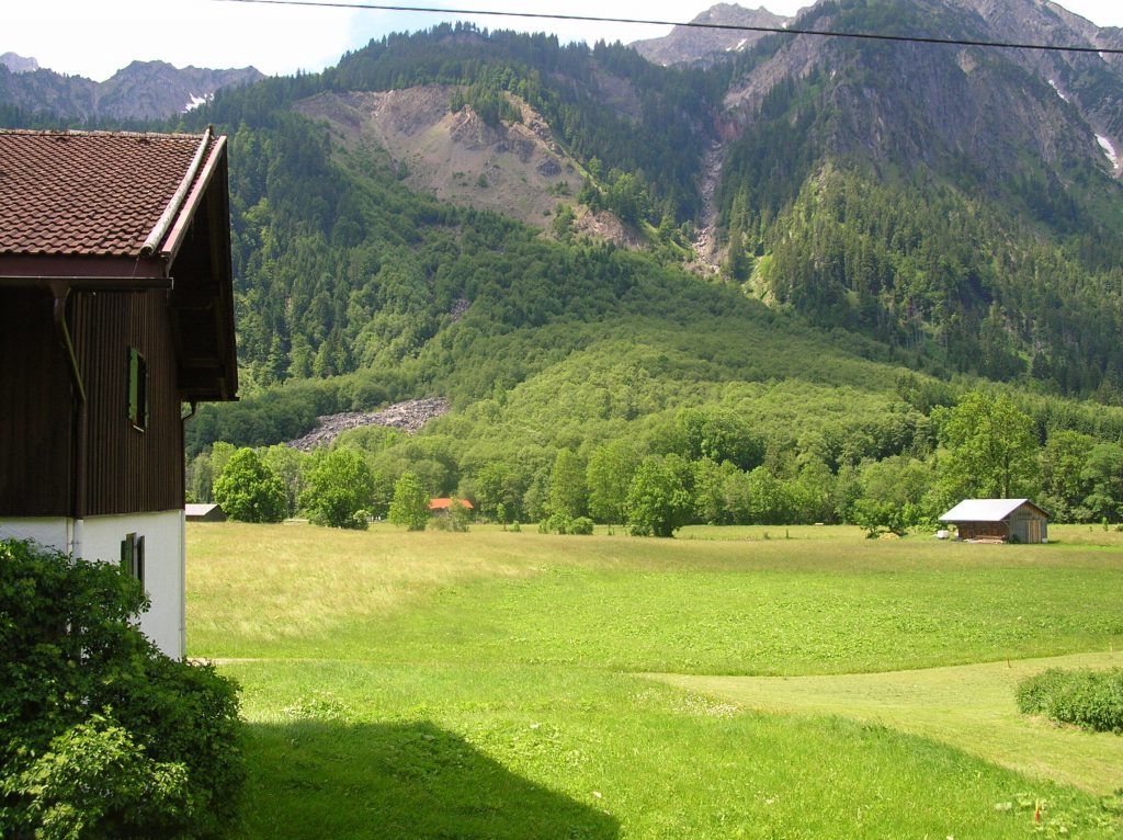
Nel mondo esistono numerose frane di grandi dimensioni e la breve lista che segue appare utile per fornire un sintetico quadro relativo alle frane catastrofiche che sono avvenute nel modo durante il XX secolo.
Molte delle frane che hanno provocato effetti catastrofici sono state causate da terremoti e da eruzioni vulcaniche.
Una delle frane catastrofiche più note è stata la valanga di detrito dal Nevado Huascaran (costa settentrionale del Perù). Nel 1970, un terremoto ha innescato, su di un versante del monte Huascaran, una valanga di detrito che ha sepolto le città di Yungay e di Ranrahirca. La valanga ha causato 18.000 vittime (il numero di vittime finale, dato dalla somma di quelle causate dal terremoto e di quelle causate dalla frana, è stato di 66.000). La stessa tipologia di frana si è verificata nuovamente, nello stesso luogo, nel 1962, causando circa 5.000 vittime.
La frana storica più grande, in termini di volume di materiale mobilizzato, è avvenuta in occasione dell’eruzione del vulcano St. Helens, nel 1980, un vulcano che fa parte della catena montuosa delle Cascade (Stato di Whashington, USA). Si è trattato di uno scivolamento di roccia – valanga di detrito, che ha causato un basso numero di vittime (tra 10 e 57, secondo diverse fonti di informazione), ma ingenti distruzioni per quanto riguarda edifici, infrastrutture viarie ecc.
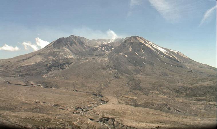
Per quanto riguarda l’Europa, la più grande frana catastrofica è lo scivolamento di roccia (con un volume di 270 m3) che il 9 ottobre del 1963 impattò ad altissima velocità il bacino idrico del Vajont. Creò onde alte 100 m che scavalcarono la diga, incuneandosi nella stretta valle del Vajont e piombando come un martello sul villaggio di Longarone e su altri villaggi limitrofi, lungo il fiume Piave. Le vittime furono 1909.
| Year | Place | Event | Cause | Deaths |
|---|---|---|---|---|
| 1933 | Sichuan, Deixi | landslide | EQ* M=7.5 | 6800 |
| 1949 | Tadzhik, Kahit | rock slide | EQ* M=7.5 | ca 15000 |
| 1958 | Japan, Kanogawa | debris flow | Typhoon | 1094 |
| 1962 | Peru Huascaran | debris aval. | ? | ca 5000 |
| 1962 | Peru Huascaran | debris aval. | ? | ca 5000 |
| 1963 | Italy , Vaiont | rock slide | Reservoir fillin | 1909 |
| 1964 | Alaska | slides | EQ* M= 9.4 | |
| 1970 | Peru, Huascaran | debris aval. | EQ* M=7.7 | 18000 |
| 1980 | Washington | debris aval. | Volcanic |
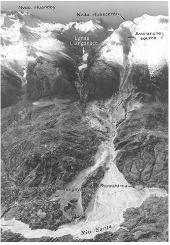
Anyhow, the world’s biggest historic landslide, in terms of volume of material involved, occurred during the 1980 eruption of Mount St. Helens, a volcano in the Cascade Mountain Range in the State of Washington. USA. It has been a rock slide – debris avalanche and the volume of material was 2.8 km³. The phenomenon began as rock slide deteriorated into 23-km-long debris avalanche with average velocity of 125 km/hr.;surface remobilized into 95-km-long debris flow The evacuation saved lives; in fact, the rock slide – debris avalanche took low deaths (only between 10 and 57 human fatalities, according to different information sources) but major destruction of homes, highways, etc.occurred

For more information go to
http://pubs.usgs.gov/fs/2000/fs036-00/
http://news.bbc.co.uk/onthisday/hi/dates/stories/may/19/newsid_2511000/2511133.stm
As concerns Europe, the largest catastrophic landslide was the rock slide (volume of 270 million m3) which on 9 october 1963, with high-velocity, fall into Vaiont Reservoir (see photo in the Landslides introductory page). It caused 100-m-high waves that overtop the Vaiont Dam, channellized into the narrow Vajont gorge, plunging like a drop hammer onto Longarone and other villages along the Piave River valley.
This phenomenon caused 1909 victims.
For more information go to 13.1 Vajont study case
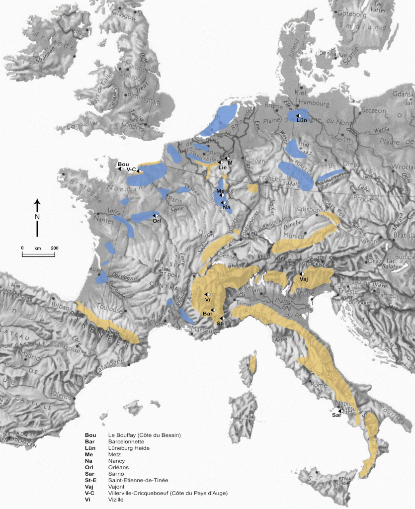
Location of the main region prone to landslides in West Europe
In blue: plateaux and plains with subsidence;
In yellow: high mountains and hilly areas
As concern the subsidence (progressive and rapid subsidence processes) in Western Europe, accordingly to the geologic conditions which advantage this phenomenon, it is mainly located in areas:
- Where natural cavities exist, i.e. in soluble bedrocks like limestone, chalk, gypsum, salt, etc. In karst areas the creation of tunnels and cavities can be very rapid when aggressive water (i.e. water with a high content of carbonic acid) dissolves soluble rocks like gypsum or salt, . In such locations the development of large cavities can occur in a few years, whereas dissolution is much slower in limestones or chalks where the development of cavities can take far more than a hundred years;
- Where anthropogenic cavities exist (subterranean quarries or mines), i.e. in the main coal, saline and iron basins (mining), and in many urban zones (quarries) (Link with study case Caen-Carries) because a lot of cities were built with stones or materials extracted in direct vicinity, and urbanization often forced the settlement into the zones of exploitation. Go to 4.1.2. Where subsidence occur in Western Europe
Shrinking is a process caused by the desiccation of the soils due to intense and/or long periods of dryness. Shrinking produces slow, low amplitude, vertical deformations of the ground surface. Shrinking can be followed by progressive swelling processes when soil humidity is increased in the wet seasons In many regions, these vertical movements have generated high damage to buildings, in particular to small single, individual houses. Go to 4.1.3. Where shrinking-swelling occur in France
References:
– DIKAU R., BRUNSDEN D., SCHROTT L. & IBSEN M.-L. (eds.), 1996. Landslide Recognition: Identification, Movement and Causes. John Wiley & Sons Ltd, Chichester FLAGEOLLET J.C., 1988. Les mouvements de terrain et leur prévention, Masson, Paris, 224 p.
Main locations of subsidence (paragraph common to progressive and rapid subsidence processes)
Accordingly to the geologic conditions which advantage subsidence, it is mainly located in areas:
- Where natural cavities exist, i.e. in soluble bedrocks like limestone, chalk, gypsum, salt, etc. In karst areas the creation of tunnels and cavities can be very rapid when aggressive water (i.e. water with a high content of carbonic acid) dissolves soluble rocks like gypsum or salt, . In such locations the development of large cavities can occur in a few years, whereas dissolution is much slower in limestones or chalks where the development of cavities can take far more than a hundred years;
- Where anthropogenic cavities exist (subterranean quarries or mines), i.e. in the main coal, saline and iron basins (mining), and in many urban zones (quarries) (Link with study case Caen-Carries) because a lot of cities were built with stones or materials extracted in direct vicinity, and urbanization often forced the settlement into the zones of exploitation.
According to Embleton and Embleton (1997) to Maquaire (2005), for some countries in Western Europe the zones prone to subsidence processes are: In Luxembourg in the Walfendigen sector: Some collapses caused by natural dissolution and the mining of gypsum. In The Netherlands near Maastricht and St Pietersberg: Subsidence caused by coal mining from 1900 to the mid 1970s, and by the marl excavation since the seventeenth century. Furthermore, subsidence is still occurring in regions where oil and gas are extracted at or close to the coastline, in particularly near the Groningue basin. Further causes for subsidence in coastal areas of the Netherlands are the compaction of Holocene sediments and a decrease of the water table pressure in recent polders. These polders have been artificially filled with a one meter layer of sand to improve the state of the built-up land (Flageollet, 1988). In Germany in the region of the Hartz Mountains and along the fringes of other central German uplands (Mittelgebirge) in Hesse, Lower Saxony and Thuringia, and also at a few localities in the north German lowlands: Soluble formations in subterranean caves have collapsed (sulphate and chloritic rocks, to a lesser extent calcareous rocks) due to karst processes. Natural karst processes, which seem to have been more active in the early Tertiary and late Pleistocene, actually show only weak effects, but mining engineering, copper and salt mining, and water pumping have intensified and modified these natural processes, sometimes leading to local damage (Garleff et al., 1997). At Lüneburg (Lower Saxony), 169 buildings were demolished between 1949 and 1973 because of subsidence caused by salt mining and the karstification of gypsum (Flageollet, 1988).
In Belgium, there are mass movements and subsidence associated with karst processes in the limestone fringe along the north of the Ardennes, in the Condroz region and also near Doornik and the region of “Pays de Herve” (Heyse, 1997). Furthermore, collapses and subsidence due to marl excavation occur regularly since the seventeenth century in the Muizenberg, associated with the marl excavation in various part of Belgium (areas of Zichen-Zussen-Bolder, Riemst, Kanne and Hoegaarden). Coal mining causes subsidence and considerable damage to buildings, roads and infrastructure in the Campine region as well as in Wallonia, in the Borinage, and in the Liège Basin.
In France, subsidence caused by human activity has been observed in the coal basins, the Lorraine iron and salt mine, above underground quarries (marl, gypsum, chalk…) in the Paris region, the North Pas-de-Calais basin, the Val-de-Loire, the Bordelais and the Touraine, the city of Caen (link Study case) ; the Pays d’Auge and the plateaux in the Seine-Maritime and the Eure. The dissolution of karst also entails subsidence, in the Paris region in the gypsum, in the Orleans region in the chalk, in the Causses du Quercy, in Perigord, etc.
Bibliography:
Embleton, C., and Embleton C. (eds.) (1997), Geomorphological Hazards of Europe. Developments in Earth Surface Processes 5. Amsterdam : Elsevier, 524p.
Flageollet, J. C. (1988), Les mouvements de terrain et leur prévention, Paris : Masson, 224p.
Maquaire, O., (2005). Geomorphic hazards and natural risks, In: Koster, E., A. (ed.), The Physical Geography of Western Europe, Oxford Regional Environments, Oxford University Press, Chapter 18, 354-377.
Ministère de l’Ecologie et du Développement Durable, 2004. Dossier d’information sur le risque Mouvement de terrains, 20 p. (à télécharger sur site du MEDD).
Liens Internet :
http://fr.wikipedia.org/wiki/Subsidence
http://www.lorraine.drire.gouv.fr/mines/g_cadreDomaine.asp?droite=2_ApresMines.asp&bas=g_MinesNavig.asp?DEST=APMINES
http://www.cgm.org/themes/soussol/mines/
http://www.cavite.net
http://www.prim.net/professionnel/documentation/dossiers_info/nat/low/mouvtTerr.pdf
http://www.catp-asso.org/cavites37/pages/missions.htm
http://clamart.cyberkata.org/
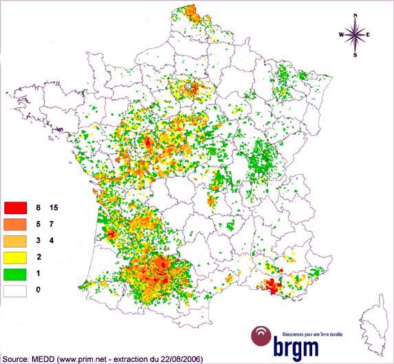
Hence, high damage related to shrinking and swelling has been recorded. Since 1989, it is more than 5 000 communes for 75 departments, which were affected par the shrinking-swelling. This phenomenon is largely distributed. However, certain areas are more particularly affected in close relation with the geological nature of the ground. It is the case in particular of the plain of Flandres, the southern part of the Basin of Paris, the graben of Limagne, the area of Apt and especially of the whole of the molassic slopes of South-west, between Agen and Toulouse and many others to a somewhat lesser extent.
In the figure we could see a number of times that a commune was recognized in a ‘state of natural disaster’ (following the law of 13 July 1982) with respect to shrinking-swelling until August 15, 2006 (from http://www.argiles.fr/)
References:
Bekkouche N. et al., 1990. Foundation problems in Champlain clays during droughts: I – rainfall deficits in Montreal (1930-1988). Revue Canadienne de Géotechnique, vol. 27, n°3, pp. 285-293.
Bekkouche N. et al., 1992. Foundation problems in Champlain clays during droughts: II – Cases histories. Revue Canadienne de Géotechnique, vol. 29, n°2, pp. 169-187.
Biddle P.J. 1983. Pattern of soil drying and moisture deficit in the vicinity of trees on city soils. Géotechnique, vol. 33, n°2, pp.107-126.
Driscoll R. 1983. The influence of vegetation on the swelling and shrinking of clay soils in Britain. Géotechnique, vol. 33, n°2, pp.93-105.
Maquaire, O., 2005. Geomorphic hazards and natural risks, In: Koster, E., A. (ed.), The Physical Geography of Western Europe, Oxford Regional Environments, Oxford University Press, Chapter 18, 354-377.
Margron P., Mouroux P. & Pinte J.C. 1988. La construction économique sur sols gonflants. BRGM-REXCOOP. BRGM Ed., Manuels et méthodes, 125 p.
Ministère de l’Environnement, 1993, Sécheresse et construction : guide de prévention. La Documentation Française, 51p.
Internet links :
http://www.prim.net/professionnel/documentation/dossiers_info/nat/low/mouvtTerr.pdf
http://www.argiles.fr/
La pericolosità da frana viene generalmente trascurata (a scala globale), rispetto ad altre pericolosità naturali quali terremoti o eruzioni vulcaniche, poiché i fenomeni franosi hanno un carattere occasionale, sono di bassa intensità e producono effetti limitati.
Eppure, alcune frane possono produrre considerevoli danni e perdite economiche, a causa della loro diversità, della loro frequenza e della loro ampia distribuzione geografica.
Le conseguenze possono essere:
- dirette (es., danni a edifici e strade)
- indirette (es., interruzione dei flussi stradali o ferroviari), in grado di produrre perdite economiche nel lungo periodo.
Al di là dei movimenti di massa di grande magnitudo, che si verificano abbastanza di rado, la maggior parte delle frane, di piccole e medie dimensioni, ha una distribuzione geografica talmente ampia da produrre danni alla società, in termini di costi, superiori a quelli determinati da eventi catastrofici.
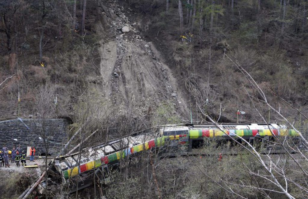
A seguito dell’impatto di una frana su di un treno diesel a due vagoni, che viaggiava sulla linea della Val Venosta, tra il Fiume Adige e le montagne, 9 passeggeri morirono e 28 vennero feriti, di cui 7 ricoverati in ospedale. Il treno era pieno di pendolari locali e di studenti. La frana, di tipo superficiale, è stata causata dall’infiltrazione di acqua nel terreno, a seguito della rottura di un tubo di irrigazione sotterraneo a servizio di un meleto. La saturazione del suolo ha raggiunto un livello tale da rendere instabile il terreno, generando uno scivolamento. La frana ha colpito il treno a 10 metri dalla sua zona di origine. Un filare di alberi, a valle del treno, ne ha impedito il ribaltamento verso il Fiume Adige, evitando una catastrofe maggiore.
Il costante aumento delle perdite, derivanti da eventi franosi a bassa magnitudo e ad alta frequenza, è spesso favorito dalle attività dell’uomo, che tendono ad incrementare la pericolosità da frana (come, ad esempio, gli sbancamenti per realizzare strade o le attività di cava) e determinano situazioni di vulnerabilità.
Inoltre, gran parte dei danni e delle vittime, generalmente ascrivibili a terremoti ed eruzioni vulcaniche, sono invece da attribuire alle frane indotte da tali fenomeni.
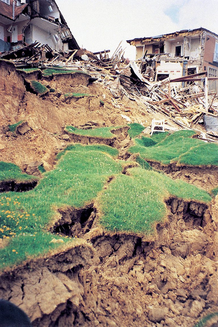
Go to 5.1 More information on consequences of landslides
Landslides consequences are generally lower compared to other types of hazards, such as seismic and volcanic hazards, as they are mostly occasional phenomena, of low amplitude and limited effects.
But some landslides cause extensive and costly damage because of their diversity, their frequency and their wide geographic distribution. These consequences could be direct (i.e. building or road damages) or indirect (i.e. perturbations, disruptions of railway, road traffic …) with economic losses during long time after the event.
Historically, one of the major landslides disasters in Europe occurred in France in 1248 when a rock fall at the Mont Granier (Savoy) destroyed 5 villages killing 2000 to 5000 people.
more details on that event >> http://www.ccsti-chambery.org/index_dos.htm (in french).
But other major disasters have caused damage and cost lives in Europe during the last decades:
• Belgium 1958: Rapid subsidence of ancient subterranean quarry at Roosburg; 18 victims;
• France 1961: Rapid subsidence in Clamart & Issy-les-Moulineaux; 21 victims;
more details on that event >> http://clamart.cyberkata.org/ (in french)
• Belgium 1961: Flow of Jupille; 11 victims and 17 houses destroyed;
• Italy 1963: Rockslide of Vajont dam; 1909 victims
more details on that event >> Go to 13.1.Vajont Case Study
• France 1970: Mudflow of Assy plateau (Hte-Savoie); destruction of a sanatorium, 72 victims;
• France 1994: Slide, Salle-en-Beaumont (Isère), 4 victims,
• Italy 1998: Mudflows of Sarno (Campania); 160 victims, 115 people injured and 1210 became homeless
more details on that event >> Go to 13.2.Sarno Case Study
Actually, besides high-magnitude mass movements which occur quite seldom, there is a huge number of medium to small sized landslides which are so widespread that the related cost for human society is even higher than that of catastrophic events. Increasing losses due to low-magnitude, high-frequency events are fostered by human activity which tends to increase landslide hazard (road cuts, quarries etc.) and favours vulnerability situations.
Furthermore, a considerable proportion of damage and casualties generally related to earthquakes and volcanic eruptions is due to landslides occurring as an effect induced by these phenomena.
Go to More details on different landslides types consequences:
5.1.1. Sinking consequences
5.1.2 Shrinking and swelling consequences (e.g. in France)
5.1.3 Slide consequences
5.1.4 Fall (rockfall avalanche, topple) consequences
5.1.5 Flow consequences
Go to 5. What could be the consequences of LANDSLIDES?
Sinking is a very slow process of vertical deformation with a limited extent (like limited progressive subsidence). The differential deformations can be caused by:
- The natural consolidation of recent soil formations (Quaternary), under load (weight of overlying grounds and additional weight of constructions). Typical examples for constructional problems/damage due to sinking are the Towers of Pisa and Bologna (Italy), and the Church Saint-Jean in Caen (France);
- The lowering of groundwater table by pumping. Typical examples are the cities Mexico, Venice, and Bangkok;
- The exploitation of fluids (like oil in California) or gas (in the Plain of the Po) in soil and rocks.
- The alternation of humidification and desiccation cycles in clayey soils (e.g. shrinking and swelling);
- The modification of the stresses in granular soils (liquefiable sands).
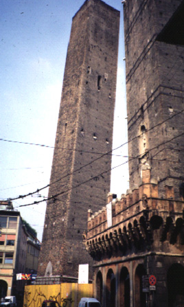
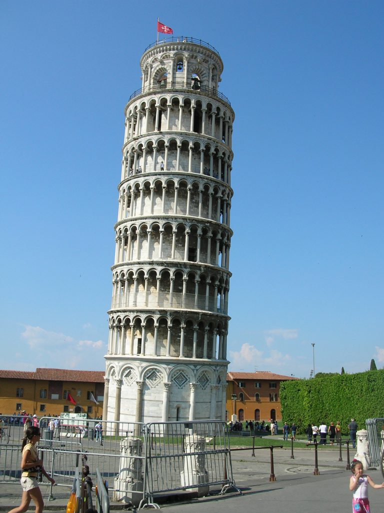

Shrinking and swelling of clayey soils constitutes a natural hazard, which is indeed less spectacular than sudden and rapid landslides. However, prolonged dry conditions have caused an intense desiccation of sensitive clayey soils. The desiccation cracks reached depths of up to two meters. Subsequent soil compression was induced by an increase in soil moisture during the wet seasons, and finally swelling of the underground. In many regions, these vertical movements have generated high damage to buildings, in particular to small single, individual houses. In France, in the period between 1989 and 1992, the amount of damages was more than 2 billions of Euros. At the end of the year 2002, the total amount of refundings carried out was evaluated to approximately 3,3 billion euros, which corresponds to several hundreds of thousands of damaged houses on the whole of France since 1989.
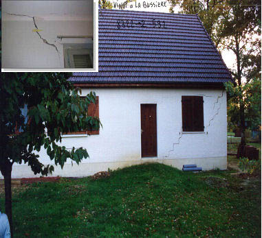
Cracks caused by shrinking of clayey soils in the Centre of France (Orléans region). In this specific case, the amplitude of the cracks is increased due to the presence of trees inducing root suction (differential sinking) (Photo: Maquaire, CERG)
Factors enforcing shrinking and swelling consequences
Differential compression can be amplified locally by tree or bush suction or by soil heterogeneity (in example, house partially located on sensitive clayey soils and on insensitive formation, e.g. limestone). This causes cracks and damage on bulding structures, and sometimes even the complete destruction of houses.
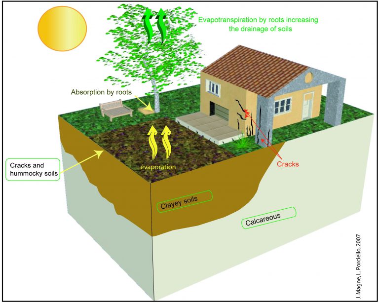
Shrinking-swelling process
Is there a specific house type which is especially vulnerable to this hazard?
The damage has often pinpointed certain deficiencies in constructions: insufficient depths of the foundations, and a high rigidity of the foundation structures and therefore inability to compensate the deformations of the underground.
A national analysis of approximately 800 cases has indicated the “typical” vulnerable construction: an individual house with a simple ground floor, a non- or inadequately steeled strip foundation, low anchoring depths (< 0.8m) in clayey soils or clayey-sandy soils, and masonry without any horizontal chaining. The susceptible soils are classed sensitive (15<Ip<30) to very sensitive (Ip>30) according to soil humidity variations (with Ip: Plastic index).
Go to 5. What could be the consequences of LANDSLIDES?
Contrary to fall events, slide events are in most cases slow phenomenon. Thus, human losses caused by slides are exceptional, but possible (figures 2 to 5). Damages to buildings are frequent, from simple cracking to total ruin. Slides can also cause interruption of roadway systems. According to the extent of the slide phenomenon, damaged area is more or less important.

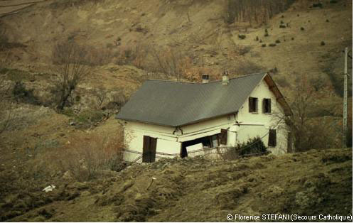
Because of very heavy rainfalls during 2 consecutive days, a 1,3 millions m3 slide triggered during the night. First a crown appeared and destroyed a house. Then a 15-meters-thick slide advanced into the gorge of a stream. Finally, 9 houses were damaged and 4 people were killed while they were sleeping (from www.irma-grenoble.com)
In 1985, in Puerto Rico, a 300,000 m3 rock-block-slide destroyed 120 houses and killed 129 people at least. This landslide was caused by extraordinarily heavy rainfalls during 24 hours. The landslide failed in 3 distinct phases between 3:00 and 4: am on October 7 1985. The first two phases involved 12 meters-thick translational slides. The third phase involved the toppling failure of a block that disaggregated and form a rock fall on the western part of the slide. Subsidiary flow failures onto the toe and from the downstream face of the toe were triggered by the heavy rainfalls and the rupture of a water pipe that emptied as much as 4 million litres of water onto the slide (Figures 3 to 5).
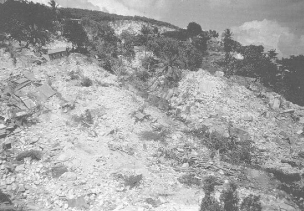
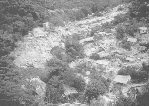
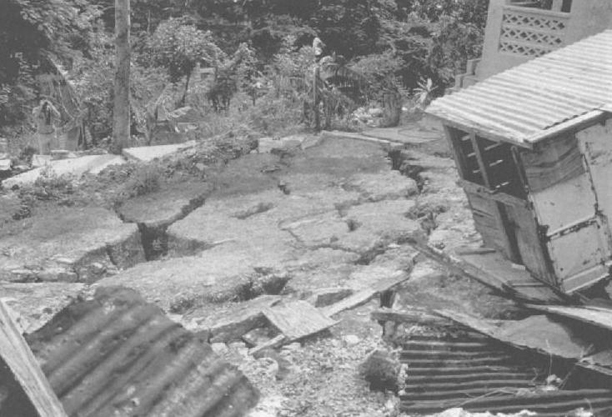
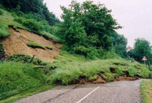
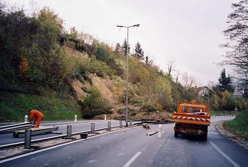
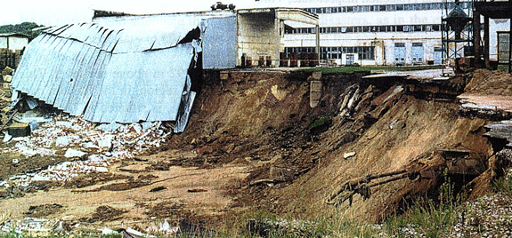
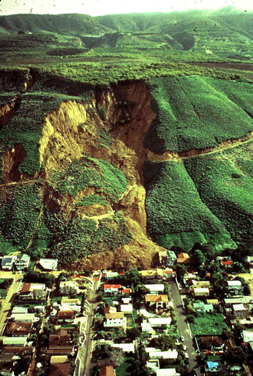
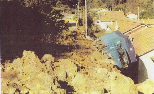
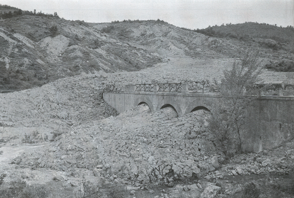
References:
LEONE F., ASTE JP., LEROI E., 1996. Vulnerability assessment of elements exposed to mass movements: working toward a better risk perception. In: Senesset K (Ed): Landslides, Proceedings of the 7th International Symposium on landslides, Balkema, Rotterdam
MALET J.P. Les « glissement de type écoulement » dans les marnes noires des Alpes du sud. Morphologie, fonctionnement et modélisation hydromécanique. PhD Thesis: Institut de Physique du Globe, Université Louis Pasteur de Strasbourg, 2003. 353 p.
MATE, METL, 1999. Plans de prévention des risques naturels prévisibles (PPR) : Risques de mouvements de terrain. Guide général. La Documentation française, Paris, 71 p.
SLOSSON E., KEENE A.G., JOHNSON J.A., 1992. Landslides/Landslide mitigation. In: Reviews of Engineering Geology, Volume IX, Colorado
Websites:
www.irma-grenoble.com
www.prim.net
Go to 5. What could be the consequences of LANDSLIDES?
Because of their sudden and (in many cases) unpredictable nature, fall events can be very dangerous for the infrastructures and the population.
Damages extent depends on energy of the falling material (function of weight and velocity). Rock falls can damage housing, interrupt roadway systems and cause human losses.

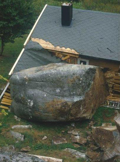
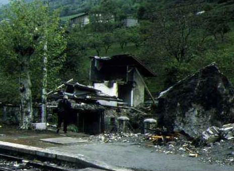
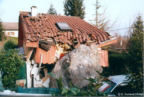
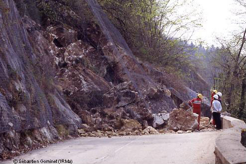
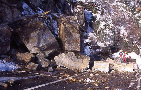
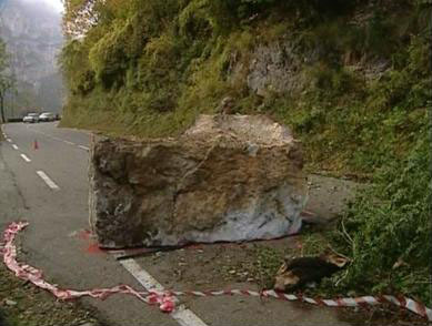
Fig. 9: Car damaged by a rock fall at Upper Island Cove, Canada, on February 14 1999. A 8 ton block toppled from the top of a 100 m slope, ran roughly 150 m, struck a house, and landed on the top of a car parked beside the house (from www.heritage.nf.ca)
Constructive layouts exist to protect housing, such as reinforcement of the exposed façade or the roof. But the best way is to avoid building in vulnerable areas and to use protection techniques.
Consequences of the rockfall avalanche process
Rock fall avalanches are incredibly destructive, they move with great rapidity and obliterate everything in their path. Perhaps the most important, once an event has occurred, is to discover whether the avalanche has dammed the valley. If it has, and a lake has formed, maximum effort must be given to take control of the breaching dam, because the resulting flow may cause a second disaster.
Consequences of the topple process
Topples are potentially very dangerous because they develop at first by loading, then by progressive basal failure and rotation, and eventually sudden collapse. This failure is dramatic, the break-up spectacular and the velocity of loose boulders and run-out high.
Damages on the infrastructures and population are the same than concerning fall risk (see details on fall).
References:
BESSON L., 2005. Les risques naturels: de la connaissance pratique à la gestion administrative. Editions Techni. Cités, Voiron, 60 p.
LEONE F., ASTE JP., LEROI E., 1996. Vulnerability assessment of elements exposed to mass movements: working toward a better risk perception. In: Senesset K (Ed): Landslides, Proceedings of the 7th International Symposium on landslides, Balkema, Rotterdam
Websites:
www.irma-grenoble.com
www.prim.net
Go to 5. What could be the consequences of LANDSLIDES?
The damages caused by a flow event depend on the quantity of material (debris, soil, mud) displaced. In the deposit areas, flows develop successive lobes and can spread on considerable surfaces. These are rapid phenomenon, thus they can be very dangerous for the infrastructures and the population. The socio-economic impact and the loss of life, property and agriculture can be catastrophic in the case of large flows through populated areas. In the case of channelized flows (debris flows), material often overflows the banks and interrupts roadway systems. The deposits are also responsible for severe indirect damages and hazards such as damming of rivers or sudden debris supply to river systems.

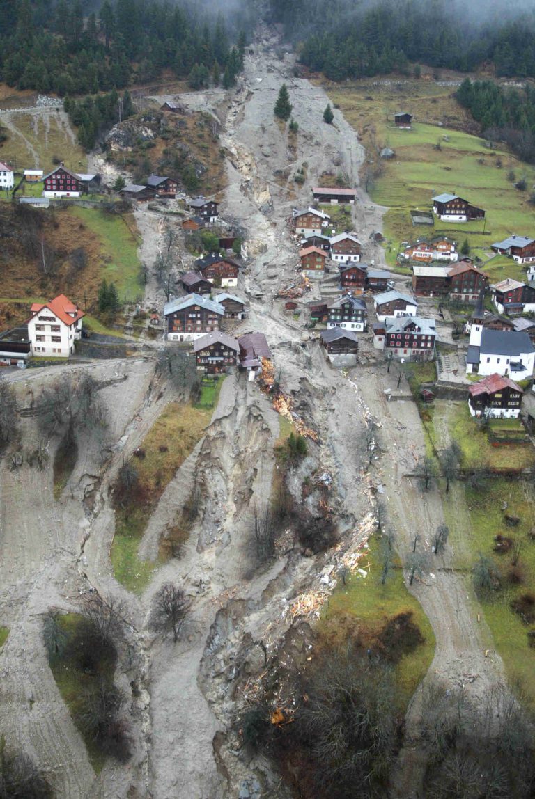
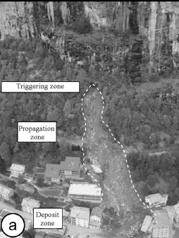
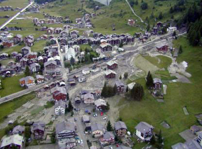
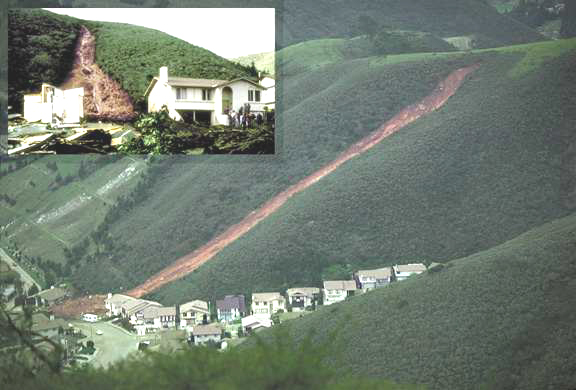
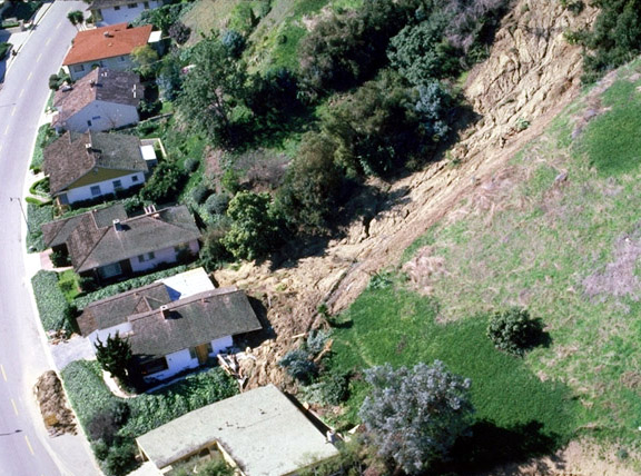
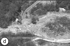
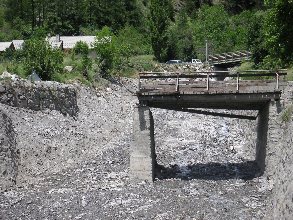
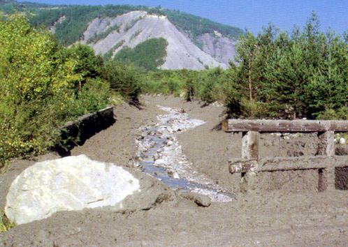
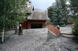
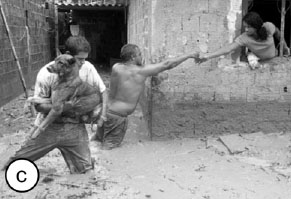
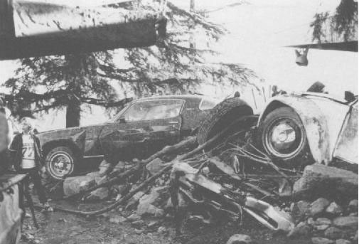
References:
ANCEY C., 2007. Notes de cours – Risques hydrologiques et aménagement du territoire. Laboratoire hydraulique environnementale, École Polytechnique Fédérale de Lausanne
LEONE F., ASTE JP., LEROI E., 1996. Vulnerability assessment of elements exposed to mass movements: working toward a better risk perception. In: Senesset K (Ed): Landslides, Proceedings of the 7th International Symposium on landslides, Balkema, Rotterdam
REMAITRE A., 2006. Morphologie et dynamique des laves torrentielles : Applications aux torrents des Terres Noires du bassin de Barcelonnette (Alpes du Sud). PhD Thesis: Laboratoire Geophen, Université de Caen/Basse-Normandie, 487 p.
SLOSSON E., KEENE A.G., JOHNSON J.A., 1992. Landslides/Landslide mitigation. In: Reviews of Engineering Geology, Volume IX, Colorado
Websites:
www.irma-grenoble.com
www.prim.net
Go to 5. What could be the consequences of LANDSLIDES?
I processi antropici (come terrazzamenti, vibrazioni, deforestazione, sfruttamento di materie prime e di acqua, escavazioni, costruzione di strade, attività di cava, sovraccarichi ecc.) possono influenzare l’innesco di movimenti franosi, agendo sulle cause esterne delle frane.
La subsidenza rapida (il rapido collasso verticale del terreno) è un collasso spontaneo, istantaneo, che produce doline o cavità di estensioni più o meno ampie (da pochi metri quadrati a diversi ettari) e di profondità variabili (da pochi metri a molte centinaia di metri). Una subsidenza rapida può verificarsi a seguito di una subsidenza progressiva.
Comunemente, la subsidenza rapida si verifica al di sopra di vuoti creati dall’uomo, come gallerie, pozzi e cave sotterranee ricoperte o miniere (ad esempio di ferro, sale, carbone ecc.).
È frequente anche nei terreni carsici, dove la dissoluzione del calcare, per mezzo di flussi d’acqua sub-superficiali, determina la creazione di vuoti (ad esempio grotte). Se il tetto di questi vuoti diviene instabile, può collassare e la roccia ed il terreno sovrastanti andranno a riempire i vuoti stessi, causando subsidenza in superficie.
Nelle zone urbane, la subsidenza rapida può causare numerose vittime: ad esempio, nel 1958 a Roosburg (Belgio), 18 persone furono uccise dal crollo di un tunnel; nel 1961, a Clamart e Issy-les-Moulineaux (Francia), 21 persone sono morte a seguito del collasso di un’antica cava sotterranea.
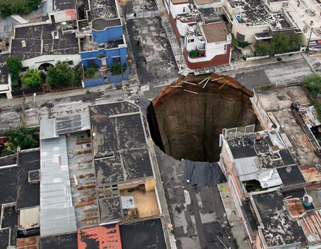
Secondo S. Bonis, un geologo al Dartmouth College nel New Hampshire, ma che attualmente vive a Città del Guatemala, ad originare una dolina non furono cause naturali, ma antropiche: probabilmente la rottura di una tubatura della rete fognaria o l’inofficiosità della rete scolante. La dolina di Città del Guatemala, larga 18 m e profonda 100 m, sembra essersi sviluppata a seguito del diluvio prodotto dalla tempesta tropicale Agata.
La cavità si è prodotta poiché la città e le sue infrastrutture sotterranee sono state costruite in una regione caratterizzata dalla presenza, nei primi 100 m superficiali, di sedimenti vulcanici (pomice), depositati durante eruzioni vulcaniche nel passato. A Città del Guatemala, la pomice non si è consolidata (non ha ancora raggiunto la compattezza simile a quella di una roccia), pertanto risulta facilmente erodibile, specialmente da parte delle acque correnti. In generale, la zonizzazione urbanistica ed i codici costruttivi, a Città del Guatemala, sono insufficienti, secondo Bonis, e le poche regolamentazioni esistenti vengono spesso ignorate. Ciò significa che tubature rotte possono rimanere tali per lungo tempo, sufficiente a determinare condizioni favorevoli alla formazione di doline di proporzioni simili a quella succitata.
Questa dolina mostra evidenti similitudini con quella formatasi, sempre a Città del Guatemala, già nel nel 2007: entrambe si sono verificate nella stessa parte della città e sembrano identiche. Questa sembra più che una coincidenza, specialmente se si collegano le tubature rotte, relative alla dolina del 2010, a quelle prossime alla dolina del 2007.
Man transforms, corrects and modifies natural processes by increasing or decreasing their rate of action and by causing the rupture of certain equilibria which Nature will try to reconstitute in different ways. With the passing of time this modifying action has assumed increasingly widespread and intense patterns.
Actually, besides high-magnitude mass movements which occur quite seldom, there is a huge number of medium to small sized landslides which are so widespread that the related cost for human society is even higher than that of catastrophic events. Increasing losses due to low-magnitude, high-frequency events are fostered by human activity which tends to increase landslide hazard and favours vulnerability situations.
Man-made processes, can influence the triggering of mass movements acting on the landslides external causes.
As regards external causes, which result in an increase of shear stresses, those processes giving rise to changes in slope geometry, mainly with an increase of the gradient, should be considered. Among these processes the following due to the human activity are particularly important: excavation, road construction, mining and quarrying, exploitation of materials or water tables overloading, deforestation, terracing etc.
In particular, human activity in the vicinity of a slope may increase the forces tending to cause failure.
Human induced modifications thay may adversely affect external loads are: i) grading of the existing slope or of adjacent slopes; ii) adjacent construction; iii) construction blast damage; iv) vibrations of passing vehicles.
Slope re-garding may result in a condition similar to that caused by natural erosion and deposition in which the toe become s oversteep or material is accumulated on the crest. Costruction adjacent to the crest of a slope can surcharge a slope. Grading adjacent to a slope can consist of excavation or filling; excavation would create oversteepened slopes, whereas filling would create a surcharge. These conditions should be anticipated or prevented so that an appropriate stability analysis can be made.
Excavation blasting can cause excessive fracturing of otherwise intact rock material. Improper blasting loosens the rocks, decreases the density and strength, and increases the permeabilità. These conditions should be recognized in the field so that slope remediation can be carried out durino or immediately after construction.
Most vibrations of passing vehicles impose small loads on adjacent slopes, but some vibrations can influente slope stability. For instance, a freight train moving on tracks a shortb distance from a steep slope with with shallow groundwater may induce vibrations at a frequency and amplitude that could cause permanent deformation or failure of the slope.
Some examples of human activity, which influenced the triggering of landslides are found in the River Panaro valley (Modena Apennines).
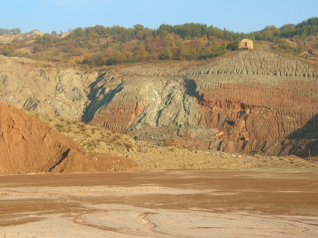
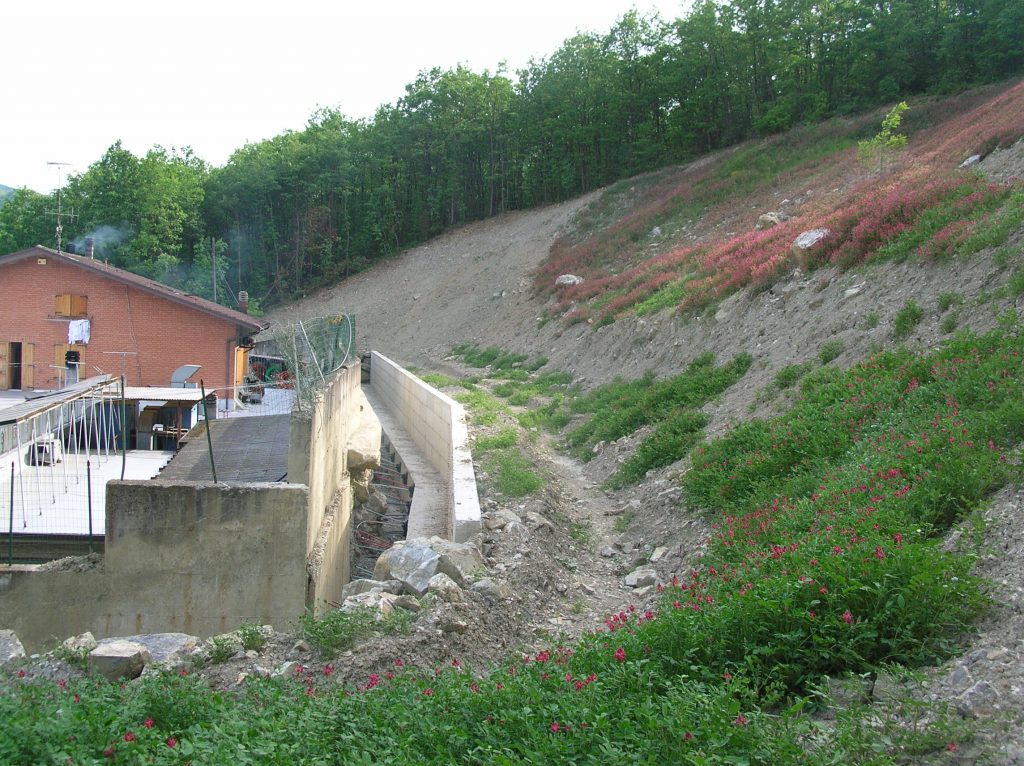
The Ca’ Bonettini landslide body (Fig. 3 and 4) resumed movement on 15th September 2003, just a few hours after a M 5.0 seismic shock .
Considering the distance of the landslide from the epicentre (35 km away in the Bologna Apennines) and the fact that locally the quake was not felt by the population but was recorded only at an instrument level, it is unlikely that a low-energy shock might be considered as the main, intrinsic cause of landslide reactivation.
Field observations, subsurface investigations and laboratory tests seem to indicate that the predisposing causes of the Ca’ Bonettini landslide could be found in the deep shrinkage fissures that dismembered the whole clayey slope as a consequence of a 3.5-month long summer drought, with a progressive decline of shear strength parameters. In addition, another important factor in further reducing stability was identified in major construction works at the foot of the landslide body, with the removal of large amounts of earth. These works were carried out without considering that the area chosen for industrial development corresponded to the foot of a dormant landslide. Therefore, the 14th September 2003 low-intensity quake was only the triggering cause of a slope movement which would have probably started all the same a few days or weeks later, as the removal of soil from the landslide foot continued as planned.
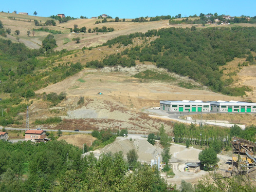
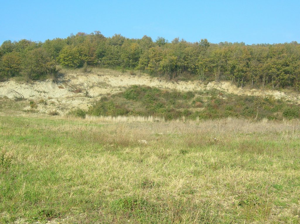
Rapid subsidence is a brutal spontaneous collapse producing sinkholes or shafts of a more or less large extent (diameter of a few meters to several hectares) and a variable depth (a few meters to many hundreds of meters). Rapid subsidence can occur after a progressive subsidence.
Commonly, rapid subsidence occurs above man-made voids, such as tunnels, wells and covered subterranean quarries or mines (iron, salt, coal, etc.) It is also frequent in karst terrains, where dissolution of limestone by fluid flow in the subsurface causes the creation of voids (i.e. caves). If the roof of these voids becomes too weak, it can collapse and the overlying rock and earth will fall into the space, causing subsidence at the surface.
In urban zones, rapid subsidence can cause numerous victims. A well known disaster occurred in 1958 in Roosburg (Belgium) when 18 people were killed by a tunnel collapse of an ancient subterranean quarry. In Clamart and Issy-les-Moulineaux (France), 21 people died as an ancient subterranean quarry collapsed in 1961.
A large sinkhole was produced by a major rock collapse on 10 february 1989 at Utsunomiya City (Japan)(Sassa1999). The plan shape of the initial sinkhole was elliptical with a length of 70 m and with of 60 m; the original ground surface (Fig.6). A factory of a building stone company collapsed into the sinkhole without casualties, fortunately, as the factory was unoccupied at that time.
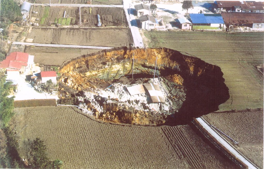
A second collapse, which enlarged the the first sinkhole, took place on 5 march 1989 (Fig.7). Its plane shape become lenticular (140 m in the NS direction and 90 m in the EW direction) and its area reached 10,000 m2. The depth of the sinkhole was about 30 m and the hole volume was estimated at 300,000 m3. A third failure occurred on 18 march 1989. It was 30 m long and 15 m wide along the western rim of the 2nd collapse.
The movement of the first collapse was largely a vertical fall or rapid subsidence. That of the second one was a combination of sinking and sliding in the northern part and sinking in the eastern part. The third one looks like a slump.
The sinkhole area is one of several important areas of stone production for building material in the Kanto region. Stone is cut in underground quarries from a Miocene Tuff formation. The tuff has been used as building material since the 8th century. The typical mining method utilizes rooms up to 10 m wide. 100 m long and 15 m high. The rooms are separated by pillars. It is not known if the the initial collapse involved a pillar failure or roof caving. People living near the sinkhole had heard sounds of low frequency for two months before the first collapse. However no cracks or deformation were recognized the ground surface. After the first collapse, many cracks were observed at the ground surface near the hole.
Important factors causing the collapse could be: I) shallow depth of the quarries (less than 40 m); ii) presence of two levels of underground workings at shallow depth over a wide area.
Since 1959, similar sinkholes due to rock collapse have occurred at least twenty time in that area as result of the underground quarrying (3 persons have been killed).
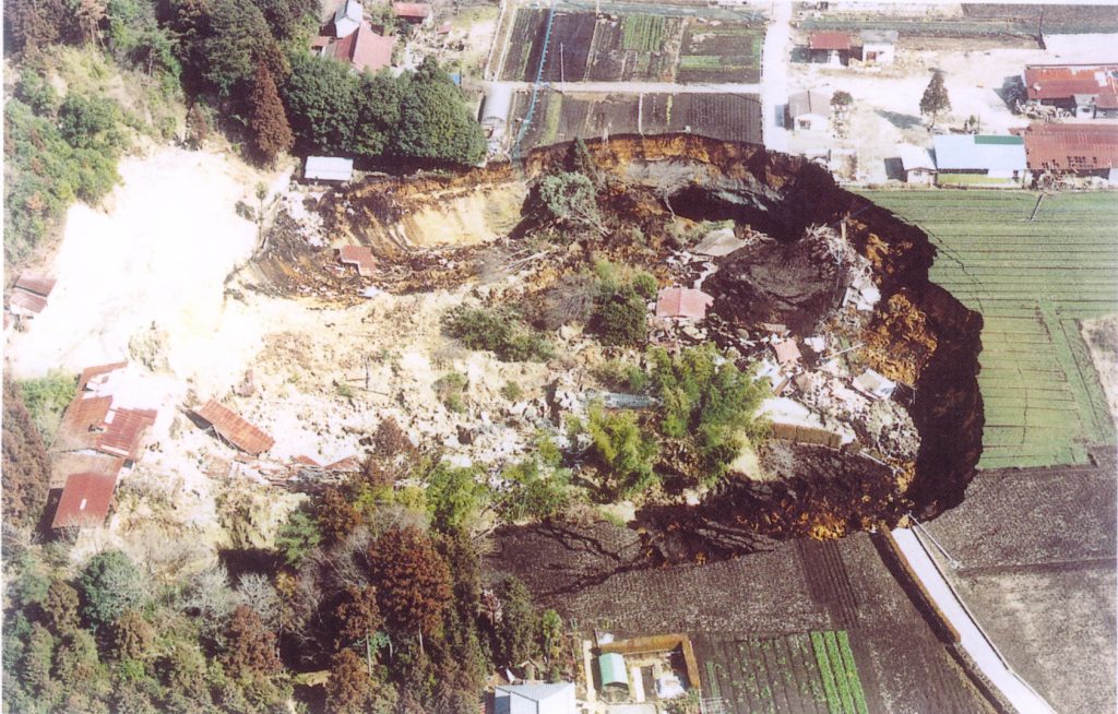
References
Embleton, C., and Embleton C. (eds.) (1997), Geomorphological Hazards of Europe. Developments in Earth Surface Processes 5. Amsterdam : Elsevier, 524p.
Flageollet, J. C. (1988), Les mouvements de terrain et leur prévention, Paris : Masson, 224p.
Maquaire, O., (2005). Geomorphic hazards and natural risks, In: Koster, E., A. (ed.), The Physical Geography of Western Europe, Oxford Regional Environments, Oxford University Press, Chapter 18, 354-377.
Sassa K. (Ed.), 1999. landslides of the world. Kyoto University Press. 413, pp
Tosatti G. (2004) –Frane del bacino del Panaro correlabili ad eventi sismici. In Mordini A. & Pellegrini M. (a cura di) – Contributi per la conoscenza delle frane dell’Appennino Modenese. Rassegna Frignanese, n.33 (2003), Tip. Benedetti. Pavullo nel Frignano, 119-136.
Tosatti G., Castaldini D, Barbieri M., D’amato-Avanzi G., Giannecchini R., Mandrone G., Pellegrini M., Perego S., Puccinelli A., Romeo R.W., & Tellini C. (2008 – Factors of seismically-related landslides in the Northern Apennines, Italy. Revista de geomorfologie.
Turner A.K. and Schuster R.L. (Ed.s), 1996. Landslides. Investigation and Mitigation. Special Report 247. National Academy Press, Washington D.C., 673 pp.
Le conseguenze delle frane possono essere influenzate dal comportamento umano in relazione alla possibilità di rispondere alle domande “dove?”, “perché?” e “quando?” un fenomeno franoso avverrà ed alla possibilità di realizzare una pianificazione territoriale adeguata.
Dal punto di vista pratico, ciò significa implementare zonizzazioni efficaci della pericolosità e del rischio da frana. In particolare, la zonizzazione della pericolosità dovrebbe essere finalizzata a prevenire l’innalzamento futuro dei livelli di rischio, da cui potrebbero derivare un numero inaccettabile di vittime e gravi perdite economiche.
In diversi paesi, lo sviluppo delle aree urbane avviene in aree soggette a fenomeni franosi, con un controllo, da parte degli strumenti di pianificazione locali, che risulta essere spesso scarso se non addirittura inesistente.
D’altra parte, la zonizzazione della pericolosità e del rischio non è un compito facile, giacché le frane sono condizionate da numerosi fattori (quali la morfologia, la geologia, l’uso del suolo) ed hanno cause d’innesco differenti (processi fisici, processi geomorfologici, processi antropici).
Un passo fondamentale, negli studi di pericolosità da frana, è spesso rappresentato dalla redazione di cartografia specialistica. Possono essere prodotte carte di base, quali le carte geomorfologiche o le carte-inventario dei fenomeni franosi, ma anche carte derivate, quali le carte di suscettività o di zonizzazione della pericolosità da frana.

The consequences of landslides can be influenced by human behaviour in relation to the possibility to answer to the questions “where?”, “why?” and “when?” a landslide phenomenon will occur and to realize an appropriate territorial planning.
From a practical point of vieuw it means to implement a reliable landslide hazard and risk zoning.
In particular, hazard zoning should be devoted to prevent further increase of risk, which could produce both an unacceptable number of casualties and economic hardship.
For example, in many countries the development of urban areas takes place in landslide prone areas with a fair or without control by a local planning.
Landslide hazard and risk zoning anyhow is not, however a simple topic because the landslides are associated with a displacement of masses due to several conditioning factors and under the effect of different triggering factors.
Go to 3.1. More informations on Factors and Causes
Go to 12.1 More information on Landslides Mapping
Several case histories teach that if the man is able to read the preliminary signs of a disaster many casualties can be avoid.
References
Cascini L,. Bonnard C., Corominas J., Jibson R. and Montero-Olarte J. 2005. Landslide hazard and Risk zoning for urban planning and development. Proc. of the Int. Conf. on Landslide Risk Management, Vancouver 31 may-3 june 2005, pp. 199-235, Ed. Balkema,
Go to 7. Can the consequences of landslides be influenced by human behaviour?
Considerando tutte le pericolosità naturali, le possibilità di previsione spaziale e temporale delle frane risultano molto buone.
Le risposte alle domande “dove?” e “perché?” una frana avverrà dipendono dal tipo di movimento e risultano abbastanza facili da affrontare se si analizzano dati di tipo geologico, geomorfologico e geotecnico.
La risposta alla domanda “quando?” si può ottenere dall’analisi dei dati climatici e dei dati relativi ai movimenti registrati.
L’innesco o la riattivazione delle frane possono essere messi in relazione a diverse condizioni meteorologiche. Nonostante ciò, alcune frane sembrano non avere alcuna relazione ovvia con le condizioni meteorologiche. Le tre condizioni meteorologiche principali, a seconda della tipologia di frana, possono essere definite come segue:
- abbondanti precipitazioni in un arco di tempo breve
- precipitazioni cumulate lungo un periodo di lunghezza variabile, con identificazione di una soglia di innesco
- precipitazioni cumulate lungo un periodo di lunghezza variabile, senza identificazione di una soglia di innesco.
L’ampia diversità dei fenomeni franosi implica l’assenza di uniformità nelle condizioni innescanti. Condizioni di instabilità possono verificarsi anche a seguito di periodi relativamente secchi, preceduti o meno da abbondanti precipitazioni annuali. Per contro, le abbondanti precipitazioni avvenute negli anni o nelle decadi precedenti possono essere sufficienti per determinare condizioni di instabilità, anche se gli anni prossimi all’innesco della frana hanno avuto precipitazioni scarse.
La tipologia di frana, ovviamente, gioca un ruolo fondamentale in questa relazione.
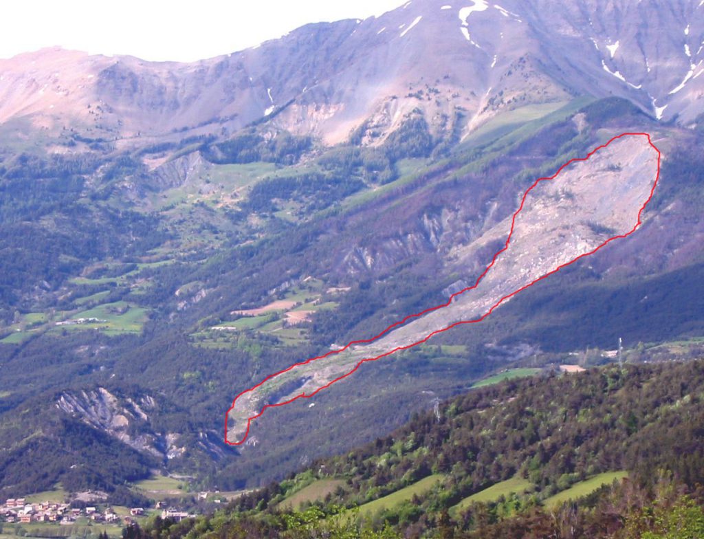
The prevention of disasters due to landslides involves defining where a given type of movement will occur – the zone in which the probability of the occurrence is greatest. The answers to the questions “where?” and “Why?” depend on the type of movement and are more or less easy to answer. Maps and documents written have been compiled by analysing geologic, geomorphologic and geotechnical data, using a historical inventory containing archives, photographs and the result of local investigations. The data may be analysed by statistical probability methods, using a GIS (Geographical Information System), for example, to demonstrate the respective weight of the various instability factors (Turner and Schuster, 1996).
The geological, geomorphological data on landslides involves research into indications of instability and the geotechnical information. The data may be analysed by statistical probability methods, using a GIS (Geographical Information System), for example, to demonstrate the respective weight of the various instability factors (Turner and Schuster, 1996).
(go to 8.1.1.More information on landslide investigation techniques)
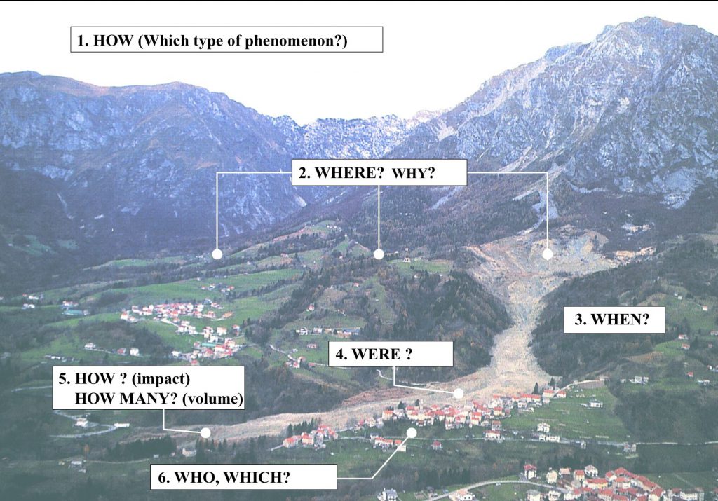
The answer to the question “When?” is obtained by analysing climatic conditions, in the vicinity or at a distance, which encourage instability and by establishing a relationship between the recorded earth movements (Maquaire, 1990; Matthews et al., 1997; Flageollet et al., 1999).
This amounts to defining the types of climate and their relationship to landslides. Flageollet et al. (1999) showed that the triggering or reactivation of landslides may be explained by several types of climate situation. However some landslides bear no obvious relation to climatic conditions, be they recent or more distant. They defined three main situations, depending on the type of landslide:
- heavy rainfall over a short period,
- cumulative rainfall over a period of varying duration with establishment of a triggering threshold
- cumulative rainfall over a period of varying duration without identification of a triggering threshold.
The great diversity of the phenomena indicated that the conditions triggering them cannot be uniform. For deep slides, they involve the analysis of rainfall over previous weeks or months and the resulting piezometric variations must be taken into account, whereas for surface mudslides it is the intensity and quantity of rain falling over previous days and hours that is most relevant. In general, at a regional level there is a wide diversity in the relationships between the different types of landslide recorded and the climatic conditions, giving rise to a number of complex combinations. As frequently observed elsewhere, rainfall is only one element of the system that accelerates or triggers landslides and is combined with other factors, such as land-use. Generally, however, it is by far the most important element of the system.
Instability can even occur following relatively dry months, whether or not they are preceded by heavy annual rainfall. Conversely, heavy rainfall in earlier years or decades can be enough to trigger instability even if little rain has fallen over the preceding years. The type of landslide, of course, plays a fundamental role in this relationship. The complexity of relations between landslides and climatic conditions makes it difficult to define “universal laws”. Before that happens, further investigation is needed into such relations in a given area, taking account of the types of landslide, their generation (triggering or reactivation), the season of occurrence and, finally, the resulting initial degree of slope stability.
The risk from earth movements can be reduced and protection can be assured by preventive or curative works of two types. Active defence tackles the causes of the active or potential and mainly involves deep drainage or reforestation. Passive defence contains the materials which are or may be in movement, which generally involve terracing, reprofiling and retaining structures. For example, in some natural or artificial underground spaces in urban zones the space is frequently filled by injecting concrete, sand and bentonite.
In high-risk cases where there is considerable vulnerability and no way of reducing the hazard level the slopes must be monitored. Generally surface movements and variations in the water level are recorded continually and an alert is sounded automatically when a fixed threshold is exceeded.
In France, for example, two main sites in the Alps are fitted with instruments – the Clapière landslide at St. Etienne-de-Tinée (Alpes-Maritimes) and the rockfall at the “Ruines de Séchilienne” near Vizille (Isère)
(http://www-lgit.obs.ujf-grenoble.fr/observations/omiv/SECHILIENNE/index.html). Some sites are also fitted with instruments to serve as observatories for scientists involved in national or international research projects, in order to provide a better understanding of the various development processes and to develop and validate predictive models. The experimental site of the Super-Sauze earthflow (Go to 13.4. Super-Sauze,Study case) in the Alpes-de-Haute-Provence has been sounded, monitored and modelled since 1995 (Flageollet et al., 2000; Malet et al., 2000; Malet et al., 2001; Maquaire et al., 2001).
(Go to 13.7. Tessina Study case. To be sent by Pasuto)
Go to 8 Can LANDSLIDES be predicted?
Investigation of existing landslides and sites of potential landslides plays an important role in landslide loss mitigation and in landslide research. Landslide investigations are used for different purposes:
- Identification and characterisation of unstable zones: triggering mechanisms? Causative factors (such as earthquakes or high rainfall events)? Estimated velocities?
- Movements monitoring: long, medium and short term behaviour of the unstable slopes? Climatic conditions?
- Movements modelling: how to explain the past movements? How to quantify these movements? How to predict future movements?
- Hazard assessment: what will be the intensity and the frequency of crisis? Which scenario has to be taken into account?
- Planning of stabilisation measures: how to decrease the movements? How to reduce the crises impacts?
Different parameters are needed to be investigated:
- Ground properties: geometry, geology, hydrology, mechanical characteristics (stresses and forces), etc.
- Surface and subsurface displacements
- Groundwater levels and pressures
Several techniques are used to determine these parameters. The figure 1 summarizes these techniques, which concern different domains such as geotechnics, geophysics, hydrology, remote-sensing:
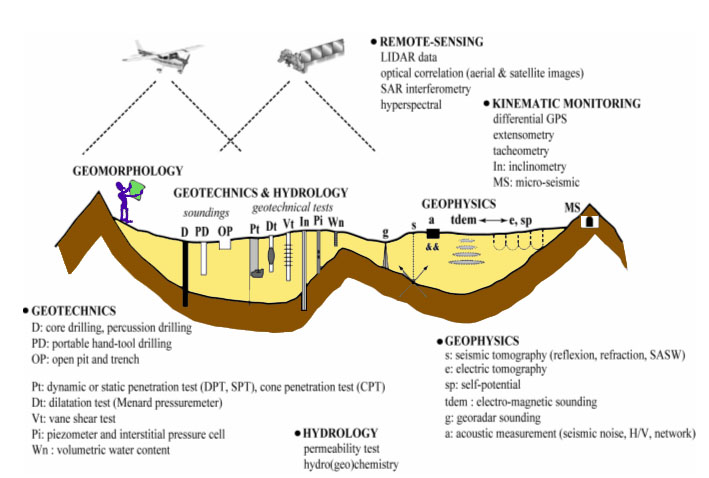
The following parts describe the different methods indicated in the figure 1.
A. Investigations of ground properties:
1. Ground geometry:
Electrical tomography is a geophysical technique for imaging sub-surfaces structures from electrical measurements made at the surface. An electrical wave is propagated through the ground between two couples of electrodes anchored at the surface (A-B and M-N, figure 2). The resistivity of the terrain is measured. The more distant the couples of electrods are, the deeper the ground is investigated. Thus, resistivity is measured between different couples of electrodes along a line (figure 2).
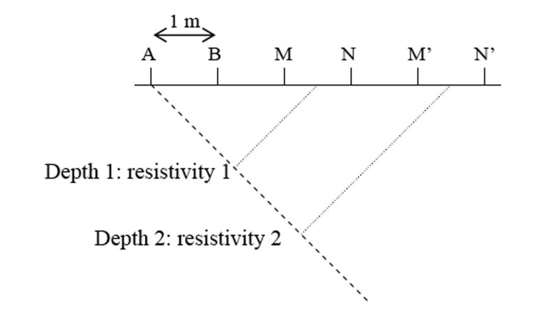
Analysis of the resistivity values allows to determine the presence of different geological layers and their properties (nature, thickness). Indeed, different materials have not the same resistivity value (from Filliat, 1981):
| Material | Resistivity (ohm/m) |
|---|---|
| Clay | 3-30 |
| Marl | 10-100 |
| Schist | 30-300 |
| Sand and gravel | 100-1000 |
| Limestone | 300-3000 |
| Crystalline rocks | 1000-10000 |
Combination of the resistivity values allows to give information about ground structure in two dimensions (2D), establishing a resistivity profile (figure 3). It is possible to image ground to a depth of 100 metres.
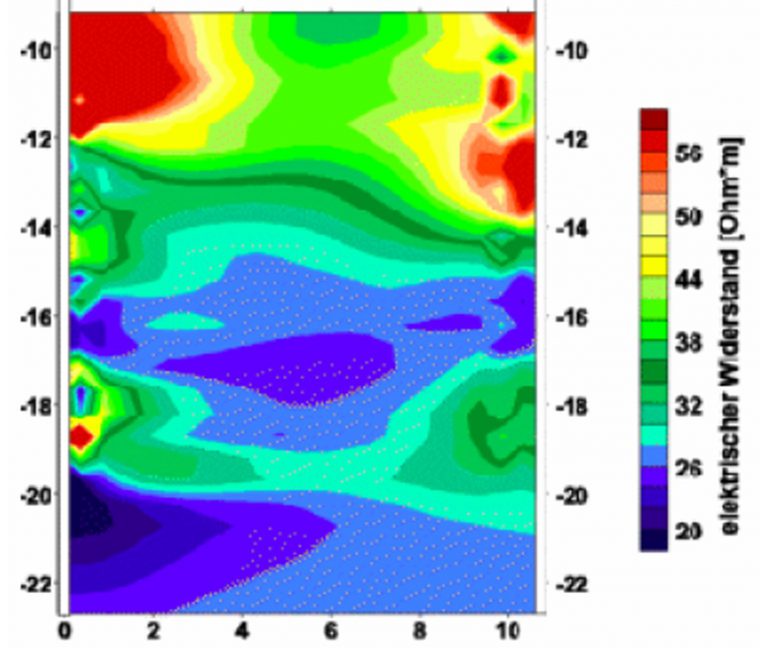
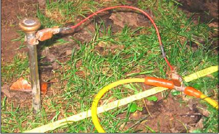
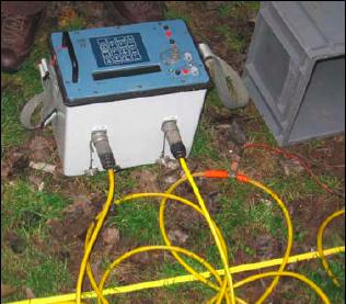
Seismic tomography is also a geophysical technique for imaging sub-surfaces structures. It uses digital seismographic records to image the interior of the ground and thus determine geometry of the stratigraphic layers. An artificial seismic wave (acoustic wave) is generated by a shaking (explosion) at the ground surface. This seismic wave is propagated through the ground, directly or by refraction or reflection. Layers of different geological nature modify direction and velocity of the wave (figure 6).
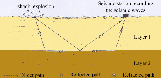
The time that the wave arrives at the seismic station is used to calculate the speed of the wave and to determine the presence of layers and some of their physical properties (density, thickness, etc.). Indeed, as the density of the material increases, the speed of the wave also increases (from Filliat, 1981):
Material Velocity (m/s)
Mud and peat 50
Clay and silt 400-1500
Sand and gravel 300-1200
Altered rocks 800-2500
Massive rocks 2000-6000
Combination of values from several transmitting and receiving stations allows to give information about ground structure in 2D or 3D.
Georadar, or Ground-penetrating radar (GPR) is an other geophysical technique for imaging sub-surfaces structures. It uses electromagnetic radiation in the microwave band of the radio spectrum, and detects the reflected signals from subsurface structures. GPR uses transmitting and receiving antennas. The principles involved are similar to seismic tomography, except that electromagnetic energy is used instead of acoustic energy: the transmitting antenna radiates short pulses of the radio waves into the ground. When the wave hits a boundary with different dielectric constants, the receiving antenna records variations in the reflected return signal (figure 7).
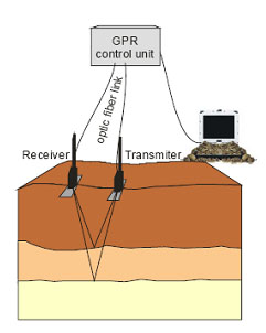
To carry out investigations on a large terrain, the distance between the two antennas remains constant and the couple of antennas is moved, or the middle between the two antennas remains constant and each antenna is moved.
The depth range of GPR is limited by the electrical conductivity of the ground (100 mS/m), and the transmitting frequency. As conductivity increases, the penetration depth also decreases. Higher frequencies do not penetrate as far as lower frequencies, but give better resolution. Frequencies between 10 MHz and 1,5 GHz are generally used.
Depth penetration can reach 50 m. Optimal depth penetration is achieved in dry sandy soils or massive dry materials such as granite, limestone, and concrete. In moist and/or clay laden soils and soils with high electrical conductivity, penetration is sometimes only a few centimetres.
2. Mechanical characteristics:
Vane shear testing is a geotechnical method. It is one of the most common in situ methods for the estimation of the undrained shear strength of soils. The equipment consists of a stainless steel vane, consisting of four rectangular blades, attached to the end of a steel rod. The vane is introduced into the ground to the depth where the measurement of the undrained shear strength is required. Then it is rotated and the torsional force required to cause shearing is calculated (figure 8). Figure 9 shows a manual vane shear test. The vane is rotated at a specified rate that should not exceed 0,1 degrees per second. The amount of rotation is specified in the green arrow whereas the red arrow has a device that measures the required Torque.
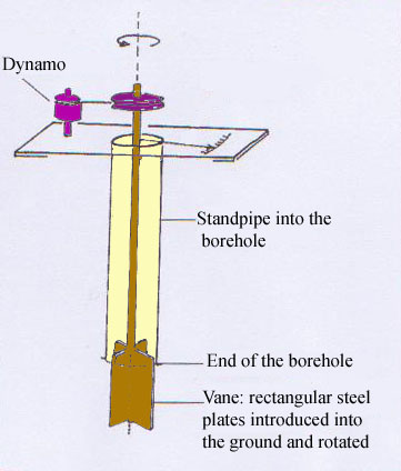
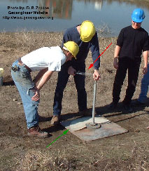
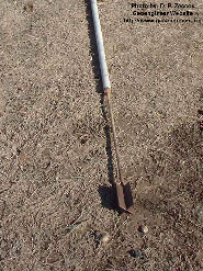
This test is particularly well suited to measurements in soft clays.
Penetration test is also a geotechnical method. Penetration can be dynamic or static. It provides information on the penetration resistance and on the density of the material.
The dynamic penetration test uses a thick-walled sample tube which is driven into the ground by blows from a sliding hammer (figure 11). The sample tube is driven 150 mm into the ground and then the number of blows needed for the tube to penetrate each 150 mm is recorded. The sum of the number of blows required for the second and third 150 mm of penetration is the “standard penetration resistance,” or the “N-value”. The blow count provides an indication of the density of the ground, and it is used in many empirical geotechnical engineering formulae.
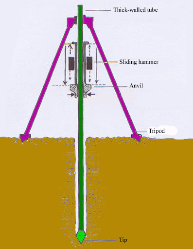
The main purpose of this test is to give information about the relative density of granular deposits such as gravels, sands or sandy clay from which it is often impossible to obtain undisturbed samples to study in laboratory. In conditions where the quality of the undisturbed sample is suspect, it is often advantageous to alternate the sampling with standard penetration tests to check the strength. The following table indicates standard values of penetration resistance for some materials (from Filliat, 1981):
Material Penetration resistance (MPa: 1 MPa = 10 bars)
Soft clay 0,02-0,2
Compact clay 0,2-0,8
Clayey sand 0,3-5
Sand 1,5-10
Sandy gravel 5-50
Finally, the dynamic penetration test is simple and inexpensive.
The cone penetration test is a static test which also measures the penetration resistance. It is rather used to investigate soft soils. It consists in pushing a cone tip into the ground at a constant and controlled rate (usually 2 centimeters/second). The resolution of the cone penetration test in delineating stratigraphic layers is related to the size of the cone tip, with typical cone tips having diameters of around 4 cm.
The original cone penetrometers involved simple mechanical measurements of the total penetration resistance. Different methods were employed to separate the total measured resistance into components generated by the conical tip and friction generated by the rod string. Now, modern electronic cones also employ a pressure transducer with a filter to gather pore water pressure data. It aids determining stratigraphy and is primarily used to correct tip friction values. Moreover, the basic penetration probe has now additional instruments such as geophones or accelerometers to allow seismic investigations, or cameras for capturing video imagery.
Finally, compared to the dynamic penetration test, the cone penetration test is gaining popularity by its increased accuracy, speed of deployment and reduced cost.
Pressuremeter and dilatometer tests are also in situ geotechnical methods, which are loading tests run up to soil failure. They consist in pushing a cylindrical probe into a borehole. The diameter of the probe can be expanded by injecting pressurized air. These stresses are exerted on the walls of the borehole at different depths in order to determine layers the most sensitive to deformations (figure 12).
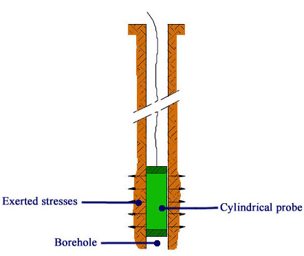
For a given depth, a pressuremeter test consists in regularly increasing the pressure and measuring the volume increment. The Menard test, which is called the normalized test must comprise about 10 steps of pressure of equal increment. The readings of the deformations are made at each step of pressure 15 seconds, 30 seconds and 1 minute after reaching the pressure level (figure 13).
Then, a pressuremeter curve V = f(P) is obtained by drawing the deformations between 30 seconds and 1 minute versus the pressures. The curve presents 3 phases: the recompression phase, the pseudo-elastic phase, the plastic phase and rupture (figure 14, (from www.roctest.com)
Parameters obtained from pressuremeter and dilatometer tests are the limit pressure (pl), the creep pressure (pf) and the pressuremeter modulus (E). The pressuremeter modulus is based on a theoretical equation (Lame) giving the radial increment of a radial cavity in function of the pressure in an elastic medium. It varies according to the nature of the material (from Filliat, 1981):
Material Pressuremeter modulus E (MPa: 1 MPa = 10 bars)
Soft clay 0,5-3
Compact clay 3-30
Marl 1,5-10
Silty sand 3-10
Gravely sand 8-100
Calcareous rock 80-20000
The creep pressure corresponds to the end of the pseudo-elastic phase.
The limit pressure corresponds to the failure of the surrounding soil. It is given by the asymptote of the pressuremeter curve. As this asymptote is not always easy to define, the limit pressure is also defined as the pressure for which the volume of the initial cylindrical cavity has doubled.
Pressuremeter and dilatometer tests are rather used in soft terrains, but can be employed in all types of terrains, with high pressures. The instruments to carry out tests in the soils and soft rocks are called pressuremeters, the instruments to carry out tests in the rocks are called dilatometers.
The Menard pressuremeter test is the most common test. It consists of a tri-cellular probe giving a uniform and radial field of stresses in the central third. The radial deformation is deducted from the measurement of the injected volume. Parasitic dilatations are reduced with coaxial injection tubing. A very large number of Menard pressuremeter tests have been already performed in various materials, giving references of the long-term behaviour of structures and confidence in the use of empirical factors (figure 15 and 16).
Other pressuremeters and dilatometers exist. They can have a mono-cellular cell, can be hydraulically pressurized, etc.
Laboratory tests also exist to assess mechanical properties of soils, such as the direct shear test and the triaxial shear test•to find the shear strength parameters of soil samples.
3. Hydrological characteristics:
Infiltrometer is a device used to measure in-situ the rate of water infiltration into soil. Both single ring and double ring infiltrometers exist, and at constant head or falling head. The Beerkan method is a simple three-dimensional infiltration test under constant head conditions, made in single cylinders. This test provides cumulative infiltration as a function of time. Measurements of particle size, initial and final water content, and dry bulk density are also required.
The cylinder is positioned at the soil surface and inserted to a depth of about 1 cm into the topsoil, to prevent lateral losses of water. The surface vegetation is removed, while the roots remain in-situ (figure 17). A fixed volume of water is poured into the cylinder at time zero, and the elapsed time during the infiltration of the known volume is measured. When the first volume has completely infiltrated, a second known volume of water is added to the cylinder, and the time needed for this to infiltrate is measured (cumulative time). The procedure is repeated for a series of about 8-15 known volumes of water. Then, cumulative infiltration time is used in infiltration equations to determine the saturated hydraulic conductivity.
Hydraulic conductivity (K) describes the ease with which water can move through pore spaces or fractures. It depends on the intrinsic permeability of the material and on the degree of saturation. Saturated hydraulic conductivity (Ksat) describes water movement through saturated media.
As Ksat increases, the permeability and thus the susceptibility to slope movement also incresases (from Musy et al., 1992):Ksat (m.s-1) 10-1 10-2 10-3 10-4 10-5 10-6 10-7 10-8 10-9 10-10 10-11
Permeability Permeable Semi-permeable Impermeable
Material Gravel Gravely sand
Coarse sand
Fine sand Fine sand
Coarse silt
Clayey silt Silty clay Homogeneous clay
Ksat is a parameter of the Darcy’s law, which is a phenomologically equation that describes the flow of a fluid through a porous medium in saturated conditions (Q: flow, H:head):
Laboratory tests also exist to determine the saturated hydraulic conductivity. The constant-head permeameter is based on the Darcy’s law. An undisturbed soil sample is collected in-situ in a known volume cylinder. Then in the laboratory the volume of water flowing through the soil sample is measured over a period of time. By knowing the volume V of water measured, length L of the sample, cross-sectional area S of the sample, time t required for the quantity of water V to be discharged, and head H, Ksat can be calculated:
B. Measurement of displacements:
The main criteria to determine slope instability is the displacement. Indeed, kinematics monitoring provides a direct check on the stability of soil and rock slopes. Large movements are nearly always preceded by small displacements and accelerations that may be detected with instrumentation of sufficient sensitivity. Structural failure is commonly associated with a gradual acceleration of displacements. The time interval between the detection of the movement and the eventual collapse of a slope depends on the characteristics of the ground and on the sensitivity and reliability of the instruments. In most circumstances, a warning period from several days to weeks, or even months, may be achieved.
1. Measurements of distances and coordinates
Investigation of surface displacements can be achieved with several instruments measuring distances. A theodolite is a conventional topometric survey technique to measure distances. It is often used to monitor settlement at the crest of a slope or along the intermediates benches on a slope face. It measures both horizontal and vertical angles. A modern theodolite consists of a telescope mounted movably within two horizontal and vertical axis. It is mounted on a tripod (figure 19).
Before use, a theodolite must be placed precisely and vertically over the target to be measured and its vertical axis must be aligned with local gravity. It can be done using a plumb bob and a spirit level. The theodolite can also be mounted on a tribrach, which consists of two triangular metal plates, which are connected at their corners by thumbscrews. The bottom plate is mounted on the tripod and by turning the thumbscrews, it is possible to level the theodolite. The theodolite can be motorized or not.
Both axis in the theodolite are equipped with graduated circles. The axis must be mutually perpendicular. The condition where they deviate from perpendicularity is referred to as horizontal axis error. The optical axis of the telescope, called sight axis must be perpendicular to the horizontal axis. If not, the deviation is called collimation error. These errors are regularly determined by calibration, and removed by mechanical adjustment (figure 20).
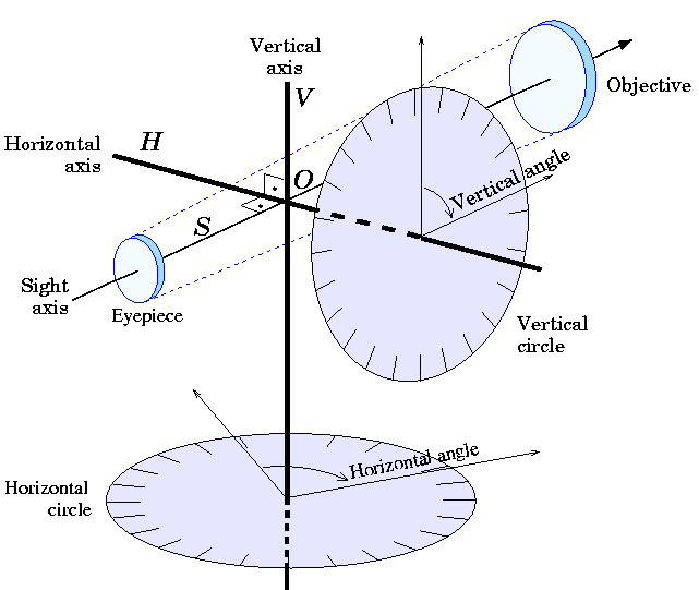
The modern theodolites employ a laser beam to measure the distances. The distance is measured with the time taken for the beam to travel from the instrument to the target. This distance between a fixed and stable instrument base and a target on the slope face can be used directly as a measure of slope movement. The accuracy of electro-optic measurement is generally from 1 to 10 mm. It is limited by atmospheric temperatures and pressure variations. Lines of sight located in zones of atmospheric turbulence should be avoided.
Alternatively the target coordinates may be determined by triangulation and trilateration calculations (figure 21).
The Global Positioning System (GPS) is a widely used instrument to measure active deformations of the Earth’s crust, providing 3-D coordinates of a target. The monitoring of landslides with GPS is usually performed using repeated campaigns, as a complement to conventional topometric methods (teodolithe).
GPS is based on a constellation of 26 Medium Earth Orbit satellites, which transmit microwave signals. Each satellite has an atomic clock, and continually transmits messages, each containing the current time at the start of the message, parameters to calculate the location of the satellite and the general system health. The signals travel at the speed of light through outer space, and slightly slower through the atmosphere.

The GPS receiver uses the arrival time to compute the distance to each satellite, from which it determines its position using geometry and trigonometry (trilateration method). A typical GPS receiver calculates its position using the signals from four satellites.
Two utilization modes exist (figure 23): absolute mode provides a “real-time” absolute position with accuracy between 10 and 100 m. Only one receiver is needed. Advantages are that this method is simple and many measurements can be made in a short time. To obtain a better accuracy, differential mode is used. Two receivers are used and the obtained position is relative. Accuracy is function of the type of receiver and the duration of observation sessions. The differential system can be static or cinematic. In the cinematic differential mode, one receiver is fixed and one is mobile (figure 24). It provides positions with millimetre-level accuracy.
Although high accuracy obtained with GPS, continuous monitoring of landslides with GPS is not usually performed because of the cost of such a system compared to conventional deformation monitoring techniques. In addition, millimetre-level accuracy can be obtained for long observation sessions (typically 24 h), it decreases with the duration of the sessions, because of errors introduced by variations of the satellite constellation and multipath effects when the radio signals reflect off surrounding terrain. However, in case of inaccessible terrains, GPS appears to be the only one method to provide reliable position measurements.
2. Use of remote-sensing techniques:
Remote-sensing is the collecting of information about an object or phenomenon by the use of sensing devices not in physical or intimate contact with the subject under investigation. Both space and aerial remote-sensing techniques exist, thus including space-borne and air-borne platforms. Interpretation of satellital and aerial photographies is widely used for many purposes in slope instability investigations. Notably, a sequence of photographs taken at suitable time intervals can be compared to examine the progressive development of slides.
There are two kinds of remote-sensing techniques. On the one hand, passive sensors detect natural energy (radiation) that is emitted or reflected by the object or surrounding area being observed. Reflected sunlight is the most common source of radiation measured by passive sensors. On the other hand, active sensors emit energy in order to scan objects and areas and then detect and measure the radiation that is reflected by the object. RADAR (Radio Detection and Ranging) is an example of active satellital remote-sensing. The most advanced RADAR technology is SAR interferometry (synthetic aperture radar).
It is a powerful tool, providing an image representing the motion with a centimetric precision and with a decametric resolution. Data acquired by SAR systems can provide digital elevation models in three dimensions. Moreover, this technique has already proven its capability to detect and to map movement fields in landslide areas. One of the currently operating space-borne radar systems is the European ERS-2 satellite, whose side-looking SAR sensor images the Earth from an orbit about 780 km above the Earth surface.
LIDAR (Light Detection and Ranging) is an other advanced remote-sensing technology similar to RADAR technology: the range to an object is determined by measuring the time delay between transmission of a pulse and detection of the reflected signal. The difference with RADAR system is that LIDAR system uses shorter wavelengths of the electromagnetic spectrum, typically in the ultraviolet, visible, or near infrared. RADAR system uses radio waves or microwaves. Then, LIDAR is a air-borne technology, instead of a space-borne technology. It is used to measure heights of objects and features on the ground more accurately than with RADAR technology.
Terrestrial photogrammetry also exists. Photographs are taken from grounds stations and are measured in a stereo comparator.
3. Measurements of surface displacements and cracks, joints and faults
Monitoring of tension cracking that develops at the crest of the potentially unstable slope can provide useful information concerning the mechanisms and directions of movement. First, it can be helpful to mark the entire length of each crack with spray paint and to delineate the pattern of cracking on plans and cross-sections of the structure. At each subsequent date of observation it is then possible to note the appearance of new cracks, and the elongation of cracks previously marked.
Then, several portable instruments are available to measure the expansion in aperture of the cracks. An example is the Demec gauge (demountable mechanical strain gauge) designed originally for measuring crack movements in concrete beams. Steel discs with a central indentation for locating the gauge are cemented on the rock surface on each side of the crack. The portable gauge employs a dial indicator actuated by a level system and is used to measure the distance between the discs.
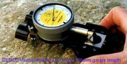
Extensometers are also employed to measure extension movements at the ground surface. Two steel or aluminium anchor bolts are secured in the ground by grouting on each side of the crack or the crown. The most common extensometer consists of an Invar cable (FeSi) tight between the two anchor bolts. One bolt is anchored in the instable area and one bolt is anchored in the stable area. One end of the cable is mounted with a pulley and one end has a freely suspended weight. Displacement of the instable material makes the cable wind round the pulley. A potentiometer connected to the axis of the pulley creates an electric signal. This signal is then converted into extension distance (figure 27).
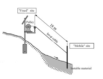
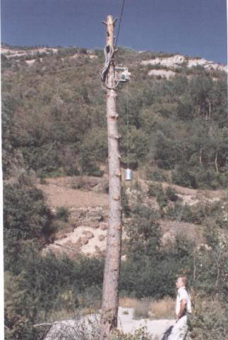
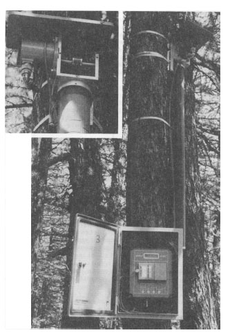
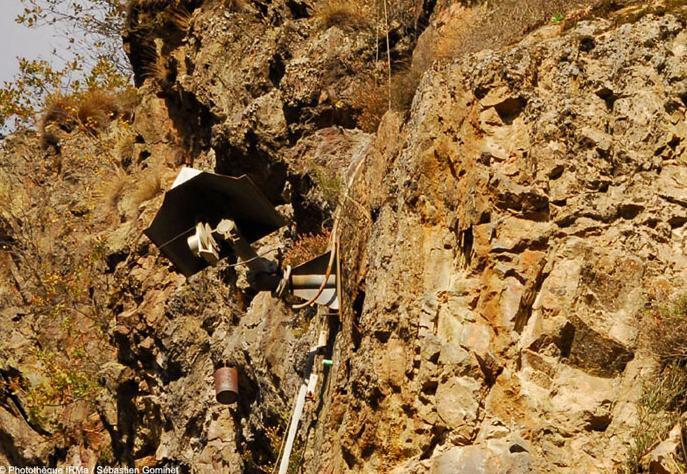
They continuously measure aperture of the most active cracks with an accuracy of 0,1 mm. The suspended weight is well visible (from www.irma-grenoble.com)
4. Measurements of sub-surface displacements
The inclinometer measures the change in inclination of a casing in a borehole and thus allows the distribution of lateral movements to be determined as a function of depth and time. In a landslide, this method is used to define the slip surface or zones of movement relative to stable zones. Inclinometer is also used to monitor dams, bulkheads and other earth-retaining structures.
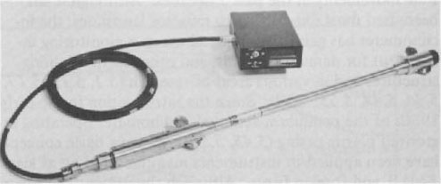
An inclinometer system has four components (figures 31 and 32):
- A guide casing is permanently installed in a vertical borehole into the ground. This casing may be made of plastic, steel or aluminium. It is fixed into the rock, so it is in movement with the slope,
- A portable sensor unit is commonly mounted in a carriage designed for operation in the guide casing,
- A control cable raises and lowers the sensor unit in the casing and transmits electrical signals to the surface,
- A portable control and readout unit at the surface supplies power, receives electrical signals and displays readings in dial or digital format.
The responses to slope changes in the casing are monitored and recorded at the surface. Readings are taken at fixed, usually equal increments throughout the entire depth. Instruments differ primarily in the type of sensor used, in the accuracy with which the sensor detects the inclination, and in the method of alignment and depth control within the borehole.
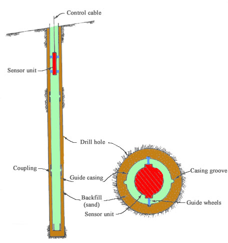
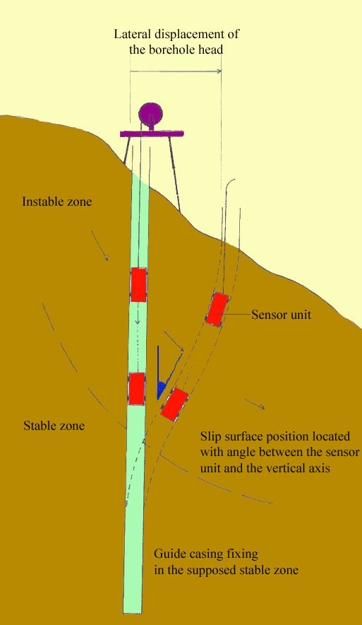
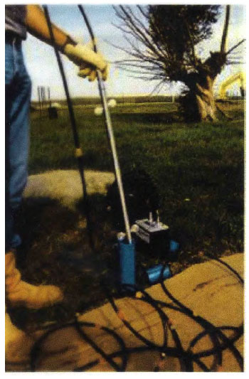
C. Measurements of groundwater levels and pressures
Groundwater has an important influence on the stability of soil and rock slopes (>>More details on the role of water). Piezometric monitoring is necessary to determine excessive water discharge or excessive water pressure.
Water pressure is monitored using a piezometer, a geotechnical method which consists of a standpipe inserted in a drillhole. The standpipe is a tube perforated at its lower end or fitted with a porous plastic ceramic element. Its end is packed with filter material (coarse sand or gravel). The remainder of the borehole is backfilled with cement grout to hydraulically isolate the piezometer. Groundwater rises in the standpipe until water head is in equilibrium with water pressure in the ground around the piezometer tip.
Groundwater pressure in the tip is monitored using a water level probe. It is a twin conductor cable with the end of each conductor connected to a brass cylinder. Entry of the probe into the water completes an electric circuit and activates a buzzer or lamp indicator on the cable reel. The cable is graduated along its length so that the distance between the water level and the collar of the standpipe tube can be measured (figure 35).
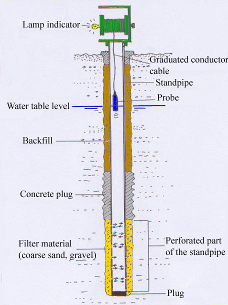
Some piezometers are adapted to measure large pressures or large pressure fluctuations. For example, water in the standpipe can take a considerable time to be in equilibrium with water in the ground around the piezometer, from a few minutes to several days. It depends of the permeability of the ground. This can be a problem when relatively rapid fluctuations in groundwater pressure are expected and when the ground is impermeable.
Hydraulic twin tube piezometer overcomes this problem, having a much smaller diameter of tube. This type of piezometer consists of a porous plastic or ceramic element connected by two flexible plastic tubes to a mercury manometer. The groundwater pressure is balanced by a head of mercury in the manometer, which is read against a calibrated scale. Generally, a hydraulic piezometer is only employed when the minimum head to be recorded is less than 8 meters below ground level.
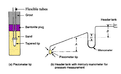
Pneumatic piezometer consists of a porous plastic or ceramic element connected to an air activated pressure cell, which is connected by flexible plastic tubes to a gauge system at the ground surface. Changes in groundwater pressure are measured by injecting air under pressure down one of the twin tubes, sufficient to balance the water pressure on the reverse side of the transducer diaphragm. The pressure sufficient to cause a return flow of air along the second plastic tube is recorded and is equal to the groundwater pressure. Only a very small diaphragm reflection is necessary to permit return flow, so that the volume change is minimal. This type of piezometer has a rapid response to groundwater pressure fluctuations.
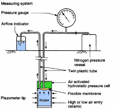
Finally, electric piezometer consists of a porous plastic or ceramic element connected to an electric transducer. Electric leads from the transducer connect the piezometer tip to the readout instrument at the ground surface. This type of piezometer has a rapid response to groundwater pressure fluctuations and may be used as an alternative to the pneumatic types in materials of low permeability, such as clays. Moreover, electric piezometer allows automatic recording of pressure fluctuations.
When installing electric or pneumatic instruments, care should be taken to ensure that the piezometer tip is thoroughly saturated with de-aired water, since even small amounts of air in the equipment lead to inaccurate readings.
For examples of application of the different investigation techniques described in this part, go to 13.3. La Valette Case Study and 13.4 Super-Sauze CaseStudy.
References:
BESSON L., 2005. Les risques naturels: de la connaissance pratique à la gestion administrative. Editions Techni. Cités, Voiron, 60 p.
BONNARD C., 2007. Introduction on landslide investigation. Mountain Risks Workshop, Switzerland, 96 p.
BRAUD I., DE CONDAPPA D., SORIA J.M., HAVERKAMP R., ANGULO-JARAMILLO R., GALLE S., VAUCLIN M., 2005. Use of scaled forms of the infiltration equation for the estimation of unsaturated soil hydraulic properties (the Beerkan method). European Journal of Soil Sciences, n°56, p. 361-374
BRUNSDEN D., PRIOR D., 1984. Slope instability. John Wiley & Sons Ltd, Chichester
CAPELLE J.F., MARCIL L., QUIRION M., HUGHES J.M. 2005. Contributions of Canadian experiments to the development of pressuremeter techniques. Symposium International ISP5-PRESSIO, 10 p. www.roctest.com
CLAYTON C. R. I., MATTHEWS M. C., SIMONS N. E., 2005. Site investigation-Chapter 10:Basic field instrumentation for site investigation. University of Surrey. www.geotechnique.info
COLESANTI C., WASOWSKI J., 2006. Investigating landslides with space-borne Synthetic Aperture Radar (SAR) interferometry. Engineering Geology, n° 88, p. 173–199
LABORATOIRE CENTRAL DES PONTS ET CHAUSSEES (LCPC), 1994. Surveillance des pentes instables -guide technique. Ministère de l’Equipement, des Transports et du Tourisme (METT), Techniques et Méthodes des Laboratoires des Ponts et Chaussées, Paris
MALET J.P. Les « glissement de type écoulement » dans les marnes noires des Alpes du sud. Morphologie, fonctionnement et modélisation hydromécanique. PhD Thesis: Institut de Physique du Globe, Université Louis Pasteur de Strasbourg, 2003. 353 p.
MALET J.P., MAQUAIRE O., CALAIS E., 2002. Le GPS en géomorphologie dynamique. Application à la surveillance de mouvements de terrain (Super-Sauze, Alpes du Sud, France). Géomorphologie : relief, processus, environnement, n° 2, p. 165-180
RocTest. Pressuremeter and dilatometer tests – Interpretation and results. 34 p. www.roctest.com
SCHULZ H., 2006. Landslide susceptibility revealed by LIDAR imagery and historical records, Seattle, Washington. Engineering geology, n° 89, p. 67-87
SLOSSON E., KEENE A.G., JOHNSON J.A., 1992. Landslides/Landslide mitigation. In: Reviews of Engineering Geology, Volume IX, Colorado
TRANSPORTATION RESEARCH BOARD, 1978. Landslides: Analysis and Control. National Academy of Sciences, Special Report 176, Washington DC
VAN ASCH T., MALET J.P., VAN BEEK L., AMITRANO D., 2007. Techniques, issues and advances in numerical modelling of landslide hazard. Bulletin de la société géologique de France, n°178, p. 265-288
Website: en.wikipedia.org
Go to 8 Can LANDSLIDES be predicted?
La prevenzione di una frana, generalmente, comprende diverse fasi successive.
- In primo luogo, occorre condurre indagini finalizzate all’identificazione dei settori maggiormente suscettibili a divenire instabili.
- Tali indagini conducono alla valutazione del pericolo da frana.
- Quindi, devono essere identificati gli elementi a rischio, valutandone la vulnerabilità, al fine di includere la pericolosità da frana nelle procedure di pianificazione territoriale.
Il risultato è una carta di zonizzazione che individua terreni ove è possibile costruire ed altri ove questo non è possibile, in base al grado di pericolosità e di vulnerabilità ivi presenti.
La prevenzione della subsidenza, come in generale per le frane, comprende diverse fasi successive, a volte adottando tecniche adattate alla ricerca di cavità. Le classiche fasi sono di seguito elencate:
- La ricognizione preliminare permette di identificare i settori maggiormente suscettibili a fenomeni di subsidenza.
- Identificazione delle cavità a partire da una selezione di specifiche zone pericolose (dalla fase 1), per localizzare con precisione i vuoti e le zone di decompressione (superfici e volume).
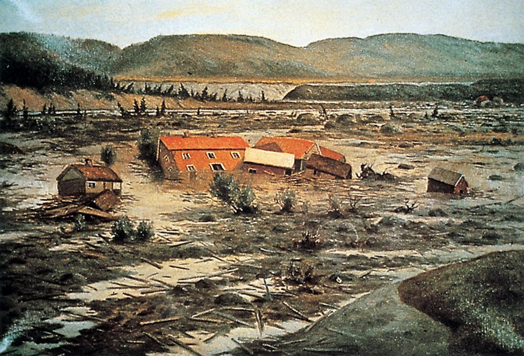
Techniques of prevention
The main implication for a planner is to ensure that there are suitable surveys of areas which are likely to produce falls. These surveys are carried out by engineering geologists and geomorphologists. The purpose of these is the identification of the sectors prone to fall. It is possible with research of surface indices such as distribution of fissures and pattern of rock discontinuities.
As concern rock avalanches, with advanced investigations and development of predictive models it is possible to identify some of the likely areas for failure and to gain some idea of the possible run-out distance for a given volume. The identification of the sectors prone to topple is possible with research of surface indices such as open cracks.
These investigations lead to fall hazard assessment. Then, elements at risk are identified and their vulnerability is assessed in order to include fall hazard in town planning. The result is a zoning map which defines terrains which can be built or not, according to the degree of hazard and vulnerability (see more information on landslide mapping). Monitoring systems should also be installed in high risk areas.
Techniques of protection
These techniques can be only used for reducing controllable and small-scale fall hazards. In high-risk and large-scale cases there is generally no technical solution. These sites require to be continuously monitored. In France, the “Ruines de Séchilienne” rockfall, near Vizille (Isère) is a good example of monitoring strategy in combination with urban planning.
Techniques of protection can be classified in two distinct categories:
– “Active techniques”: they avoid the triggering of the fall. They mainly consist in reinforcement systems which retain the material (rock or soil) on the steep slope or the cliff.
– “Passive techniques”: they seek to control the consequences of the fall. They aim at interposing a “screen” between the steep slope and vulnerable elements.
A. Active techniques:
– Steel reinforcement
Reinforcement systems add strength to the rock mass by increasing the general tensile strength and by improving its resistance to shear along discontinuities. Both active and passive steel reinforcement systems are used for stabilizing rock slopes. The active system involves tensioned or prestressed bars or cables that have been anchored at one end within the rock mass by mechanical means or by cement or chemical grouts or by both. The passive system involves untensioned bars that have been fully grouted throughout their length by cement or chemical grouts. The main advantage of the active system over the passive system is that no movement has to take place before the anchor develops its full capacity; thus, deformation and possible tension cracking of the slope are minimized. Long-term corrosion protection of the anchors must be provided.
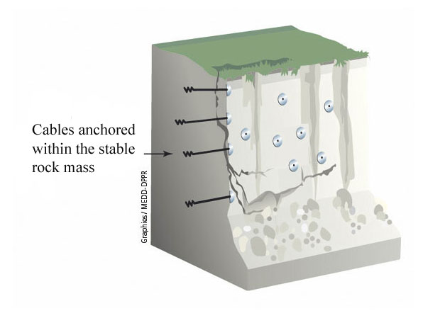
Length of bars or cables can vary from few meters to several tens of meters. Rock bolts are commonly used to reinforce the surface and near-surface rock of the slope. Tendon and cable anchors are used for supporting large masses of unstable rock and are accordingly longer than rock bolts. Short reinforcing bars fully grouted into the rock mass are commonly called dowels. Their action is somewhat similar to rock bolts.
The rock bolt exerts a compressive force, which tends to prevent elastic rebound, frost action phenomena, and general relaxation or exfoliation by keeping the rock in its original position. Shear resistance along discontinuities is improved. Rock bolts are often used to minimize the decompression or loosening effects associated with recently excavated rock slopes. Figure 2 shows a group of large diameter bolts concentrated on an area at the base of a slope to maintain the integrity of large fault blocks.
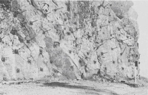
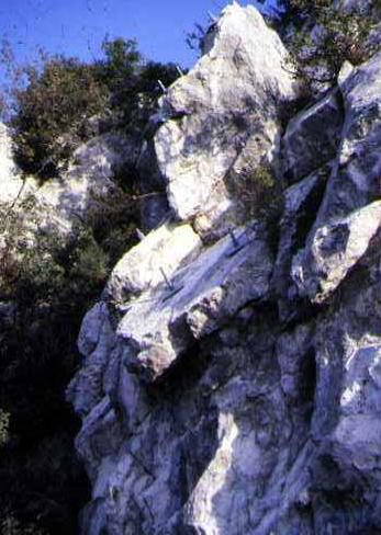
– External support systems
They offer resistance to loads imposed by the slope-forming materials.
Buttresses and bulkheads are designed to take part of the weight of the slope, thus inducing stable conditions and preventing rock falls. They are used for stabilization where failure of overhangs appears to be imminent or where slight cracking or vertical displacement appears to be occurring. Buttresses are usually constructed at highway or railway level.
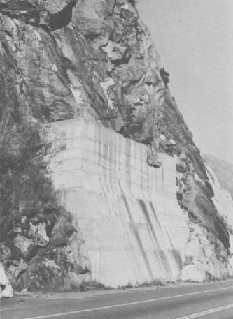
Retaining walls are used to prevent large blocks in the slope from failing and to control or correct failures by increasing the resistance to slope movements. The space along railways and highways is often too narrow for normal gravity walls, but tied-back walls may be used to overcome this problem. They need only have the strength required for bending and shear resistance between rock bolts. Figure 5 shows an application of a tieback retaining wall formed of galvanized steel members for protection of a high sedimentary road cut.
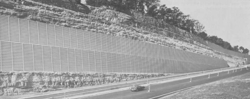
The box gabion catch wall is a rectangular basket divided by diaphragms into smaller rectangles that are filled with stones. The basket is formed of hexagonal steel galvanized wire mesh. The wire mesh tends to reinforce the stone in tension. The gabion is a flexible structure that tends to deflect and deform instead of breaking by rock impact. Gabion catch walls are recognized as a feasible alternative to more rigid concrete walls for protecting the roads from rolling stones as large as 0,6 to 1 meter.
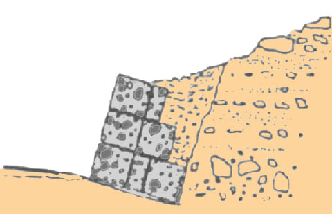
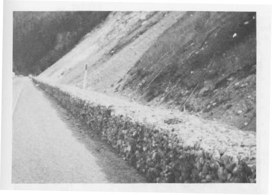
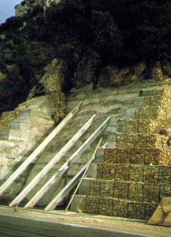
– Shotcrete
It is a concrete that consists of mortar with aggregate and that is projected by air jet directly onto the surface to be treated. It is used to prevent weathering and spalling of rock surfaces and to provide surface reinforcement between blocks. The shotcrete acts as a protective membrane on the surface of the rock and helps to maintain the adjacent rock blocks in place by mean of its initial shear and tensile strength. Shotcrete can be used in combination with steel wire mesh and rock bolts to give structural support and also to form buttresses for small loads (figure 9).
The most important advantage of shotcrete in treating rock slopes is that offers a rapid, mechanized and often uncomplicated solution to rock fall problems. Deterioration of shotcrete can result from frost action, groundwater seepage, or rock spalling due to lack of shotcrete bond.
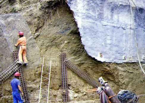
– Rock face purge
Instable rock or fall is artificially caused. The aim is to obtain a bare rock face and thus to eliminate fall risks. Different techniques are used to cause the fall, such as mining, chemical grout into boreholes, hydraulic breaking out, etc. Purge is a temporary protection technique because the bare rock will be submitted to fragmentation phenomena, frost action, and will be more liable to fall again. Therefore, rock face purge requires regular monitoring.
B. Passive techniques:
– Intercepting slop ditches and shaped berms
Slope ditches are used to intercept rock falls partway up the slope. Shaped berms are used at the top of the slope or can be installed in combination with a ditch. These methods ensure that rock falls get caught while they are on their way down the slope. The shaped berm is generally 4-6 m high, material (soil) is compressed and upstream face is often reinforced with gabions or tyres (figure 10). Depending of the nature of the terrain, ditches and berms are generally simple to construct and easy to maintain. An intercepting slope ditch should only be installed on a slope that can accept the introduction of a ditch without the stability of the entire slope being impaired.
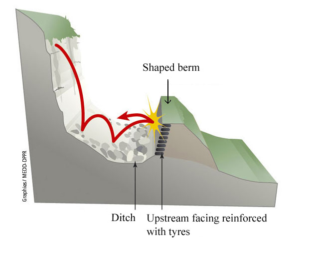
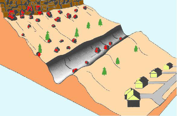
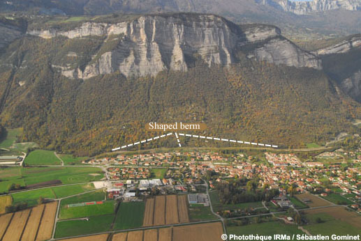
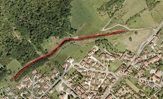
– Anchored wire mesh
It is a versatile and economical material for use in protecting the right-of-way from small rocks. Layers of mesh are often pinned onto the rock surface and installed as a drapery to prevent small loose rocks from becoming dislodged. They also can be used to guide falling rocks into a ditch at the base of the slope. This practice is commonly used on talus slopes in steep mountainous terrain. Mesh can be combined with long rock bolts to provide a generally deeper reinforcement. Conditions for the use of mesh are particularly suitable if no individual rocks are larger than 0,6 to 1 meter and if the slope is uniform enough for the mesh to be in almost continuous contact with the slope.
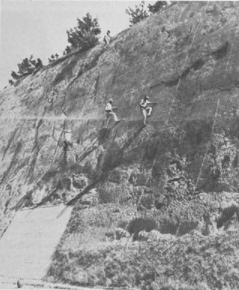
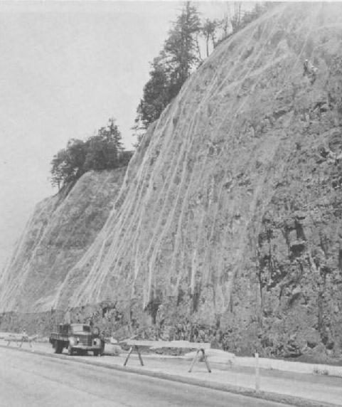
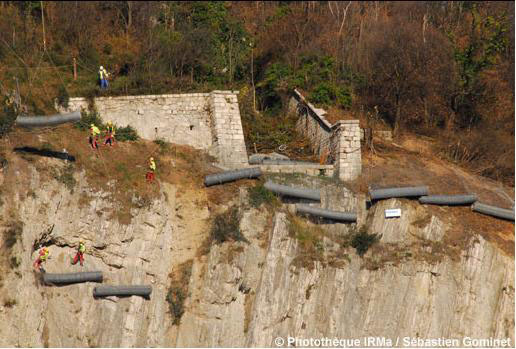
Anchored wire mesh can be installed at toe of rock face or on the slope and not only as a drapery onto the rock surface. They aimed at dissipating the kinetic energy of the rolling rocks and stopping their trajectory.
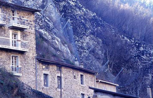
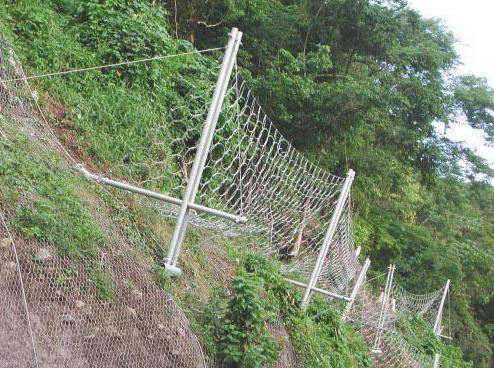
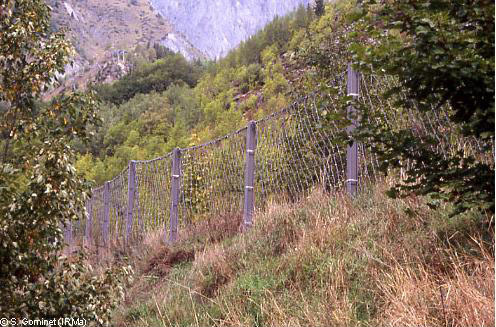
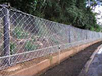
– Rigid fences
Rail walls consist of vertical posts and horizontal members that are extended between the vertical posts. The posts are usually scrap steel rails set in holes backfilled with concrete. The horizontal members are either ties or scrap rails. These rigid protection systems are generally less efficient than flexible screen such as wire mesh.
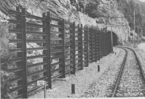
– Role of forest
Vegetation has positive and negative effects on slope stability (More information on landslide causes). Within the framework of fall risk prevention, forest can act as a natural barrier to intercept rolling rocks.
A team of researchers of Grenoble, in France, is currently working about the protection function of forest against rock fall hazard. Different in situ experiments are led to reconstruct natural rock fall and rocks trajectory. Trajectory modelling will be developed, in order to be used by local practitioners.
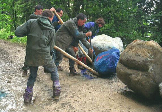
First studies showed that for a slope between 25 and 35°, forest plays an important protection role, stopping 80 % of rocks. Protection effect of forest acts on stop distance and bounce height of rocks. An experiment has been led with a 3 tons boulder rolling at 80 km/h with 2,5 meters high bounces. Forest stopped the boulder 80 meters further. Researches are also led with different tree species. Such studies contribute to develop long-term strategies for natural hazards prevention.
References:
– BESSON L., 2005. Les risques naturels: de la connaissance pratique à la gestion administrative. Editions Techni. Cités, Voiron, 60 p.
– BRUNSDEN D., PRIOR D., 1984. Slope instability. John Wiley & Sons Ltd, Chichester
– DIKAU R., BRUNSDEN D., SCHROTT L. & IBSEN M.-L. (eds.), 1996. Landslide Recognition: Identification, Movement and Causes. John Wiley & Sons Ltd, Chichester
– MATE, METL, 1997. Plans de prévention des risques naturels prévisibles (PPR). Guide général. La Documentation française, Paris, 76 p.
– NATIONAL RESEARCH COUNCIL, 2004. Partnerships for reducing landslide risk. Assessment of the landlide hazards mitigation strategy. The National academies press, Washington DC
– SLOSSON E., KEENE A.G., JOHNSON J.A., 1992. Landslides/Landslide mitigation. In: Reviews of Engineering Geology, Volume IX, Colorado
– TRANSPORTATION RESEARCH BOARD, 1978. Landslides: Analysis and Control. National Academy of Sciences, Special Report 176, Washington DC
Websites:
www.irma-grenoble.com
www.prim.net
Techniques of prevention
Flows processes analysis is complex because it concerns both geotechnics, geomorphology domains (as for landslides in general) and hydraulics domain. Thus, prevention and protection techniques must also concern these different domains.
Flow triggering is mainly caused by heavy rainfalls; prevision of rain falls events is possible thanks to predictive models, however they concern large areas and not small watersheds in which flows occur. Moreover, flows events are characterized by the rapidity with which they propagate in response to a rain fall event. Thus, prediction of flow events is difficult or even impossible.
The best way for flow prevention as for landslides in general is to control urbanization by a zoning map which defines terrains which can be built or not, according to the degree of flow hazard and vulnerability (see more information on landslide mapping).
Moreover, prevention techniques consist in regularly maintaining the main channel and the banks in order to avoid blocking of the channel by trees for example, liable to aggravate the consequences of the flow.
Techniques of protection
A flow is generated because of a great quantity of material is available for sediment transport on the slopes of the watershed. According to this, techniques of protection can be classified in two distinct categories:
– “Active techniques”: they avoid the triggering of the flow. They mainly consist in reducing sediment transport by acting on source areas, by reducing slope erosion processes.
– “Passive techniques”: they seek to control the consequences of the flow. They mainly consist in slowing down the flow by acting on the stream channel.
A. Active techniques
– Role of vegetation
It is admitted by scientific community that vegetation acts on slopes by reducing runoff and erosion processes. Planting is considered as a long-term and efficient strategy for preventing sediment production. From the end of the 19th century large reforestation works have been carried out in French mountainous areas in order to reduce the frequency of mud flows and debris flows. For example, 1000 ha have been planted on highly erodable slopes of the Riou-Bourdoux catchment, in the Barcelonnette Basin. Even if the torrential activity did nit disappear, the frequency of flows rapidly decreased (figure 1).
Fig. 1: Evolution of the forests surfaces between 1896 (a) and 2000 (b) in the Riou-Bourdoux catchment (from Delsigne and al., 2001)
A technique is to build at different levels in the slope banks with wire mesh in order to reduce runoff and improve planting of herbaceous species or shrubs. These banks can also be made off wooden posts (figure 2).
Fig. 2: Slope planting with banks in Isère, France. Evolution of the slope between 1898 (a), 1912 (b), 1988 (c) (from Besson, 2005)
– Correction works in gullies
In order to prevent gullying and erosion processes, small dams can be built across the gullies in combination with planting. These dams can be made of concrete, gabions, grids, geosynthetics or wire mesh anchored by steel or wooden posts (figure 3).
Figure 3: Gullies correction with wire mesh small dams (from Besson, 2005)
B. Passive techniques
While active techniques rather correspond to bio-engineering (planting techniques), passive techniques rather correspond to civil engineering.
– Stabilization dams in the stream channel
These works aim at stabilizing the river profile. Indeed a stream tends to erode its banks and bed in steep slopes and to deposit material in gentle slopes in order to reach an equilibrium profile. Therefore, the upstream part of the channel tends to recede.
Torrential correction consists in building dams in the cross section of the channel in order to attenuate energy of the flow and provoke deposit of material upstream each dam. The purposes are to reduce erosion of the channel and quantity of material reaching the alluvial cone and liable to damage the human infrastructures. The dams also allow stabilization of the banks (figure 4).
Sizing of the dams requires for the planner to consider hydraulic behaviour of the stream, natural equilibrium slope of the channel and sediment transport processes. Dams must be frequently maintained because they can be damaged by major flows (figures 5 and 6).
Fig. 4: Correction of a stream profile with dams. a: natural profile which tends to retreat by erosion process (1 to 4). b: stabilized profile with dams (from Besson, 2005)
Fig. 5: Dams in the Faucon stream, Barcelonnette Basin, France (from Remaître, 2006)
Fig. 6: Damaged dam in the Faucon stream (from Remaître, 2006)
– Deposit area/sediment trap
It aims at slowing down the flow and provoking deposit of the materials.
– Dykes
It aims at protecting the banks from erosion and preventing the flow from overflowing. It usually consists of reinforced concrete walls or gabions walls. Anchor of the wall must be carefully designed in order to prevent erosion at the bottom of the wall.
References:
BESSON L., 2005. Les risques naturels: de la connaissance pratique à la gestion administrative. Editions Techni. Cités, Voiron, 60 p.
DELSIGNE F., LAHOUSSE P., FLEZ C., GUITER G., 2001. Le Riou Bourdoux :un « monstre » alpin sous haute surveillance. Revue Forestière Française, p.527-540
REMAITRE A., 2006. Morphologie et dynamique des laves torrentielles : Applications aux torrents des Terres Noires du bassin de Barcelonnette (Alpes du Sud). PhD Thesis: Laboratoire Geophen, Université de Caen/Basse-Normandie, 487 p.
Methods and techniques of prevention and repairing of the damages due to slow subsidence are the same of rapid subsidence.
Prevention of subsidence, as for landslides in general, corresponds to a step comprising several successive stages sometimes requiring adapted techniques to seek cavities (Côte et al., 2005 ; Pothérat, 2005). The following stages are classically retained:
1. Preliminary recognition allows an identification of the sectors prone to subsidence. This step comprises:
(a) a preliminary stage consisting of a geological expertise to identify the grounds prone to dissolution (natural cavities) or exploitation (anthropogenic cavities). Information is then completed by an investigation of archives, ancient maps and plans, interviews (population and organizations), etc. In France, there exists a national database on underground cavities “BDCavité”;
(b) a research of surface indices by using remote sensing techniques such as photo-interpretation of vertical or oblique photographs, infrared thermic radiometry, accomplished with ground validation (research of morphological indices, etc.)
2. Detection of the voids starting from a selection of specific hazard zones (achieved in stage 1), to precisely locate voids and decompressing zones (surfaces and volume) by:
(a) sub surface geophysical methods: microgravimetry to obtain a map of geophysical anomalies, and other seismic or electromagnetic methods, ,.
(b) drillings with instantaneous or differed diagraphs (??) and videoscopy in drillings,
(c) exploration, if accessible, and cartography.
3. Interpretation, monitoring and hazard assessment.
4. Identification of elements at risks and assessment of their vulnerability
5. Risk mapping (in 3-4 levels).
Main techniques of protection are classified in two distinct categories (MEDD, 2004):
A. ‘active techniques’ to avoid the triggering of the movement. They consist in supporting and consolidating the cavities to avoid subsidence. For instance, it is possible to reinforce existing pillars or to reduce the distance between the pillars:
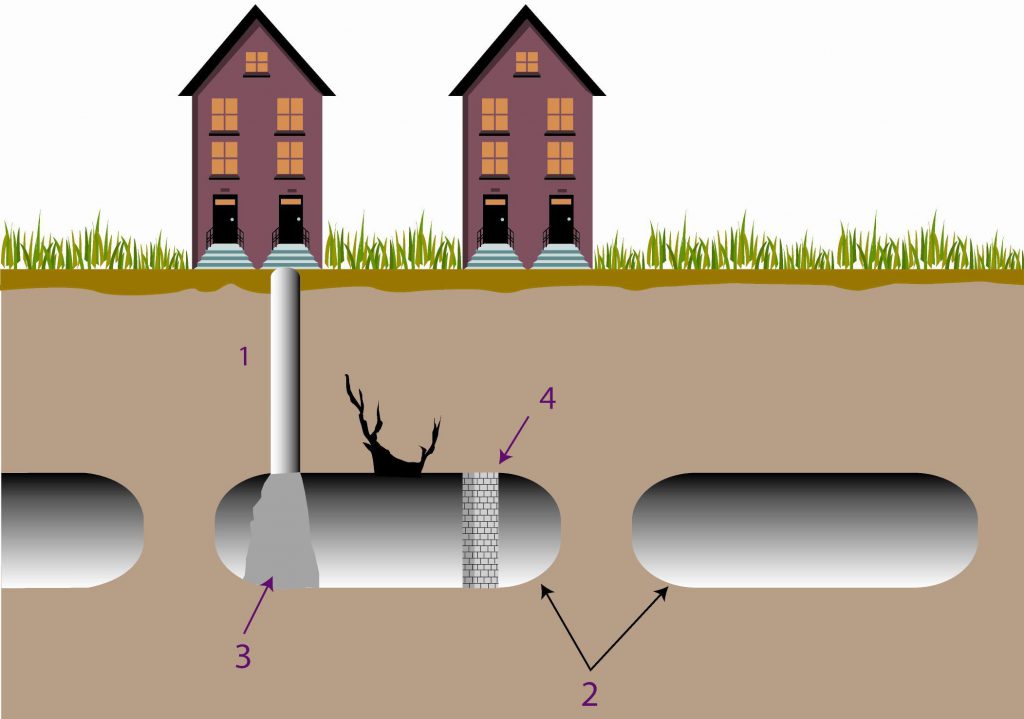
– by arranging additional pillars, by the construction of new pillars in masonry in the accessible cavities or a grouting (mixture of concrete and additives) forming studs in the inaccessible cavities (with 1: pile; 2: natural or artificial caves; 3: grouting forming stud; 4: pillar in masonry).
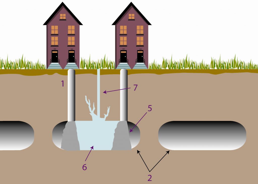
– by filling the cavity by thorough fill (if it is accessible) or by gravitating injection of liquid mortar (generally, mixture of sand, bentonite and additives) after installation of containment walls (with 1: pile; 2: natural or artificial caves; 5: liquid mortar forming containment wall; 6: filling liquid mortar; 7: injection drill).
If the cavity is close to the surface, it is essential to control the water infiltrations which could accentuate the phenomenon
B ‘passive techniques’ which seek to control the consequences of subsidence. They aim at reinforcing the structures of threatened constructions (by peripheral chaining, etc.) so that they do not undergo the consequences of the relative settlements. The realization of deep foundations, crossing the cavity, can be a means of protecting. Lastly, the buried networks must be flexible to adapt to the deformations (regular controls of their sealing must be envisaged).
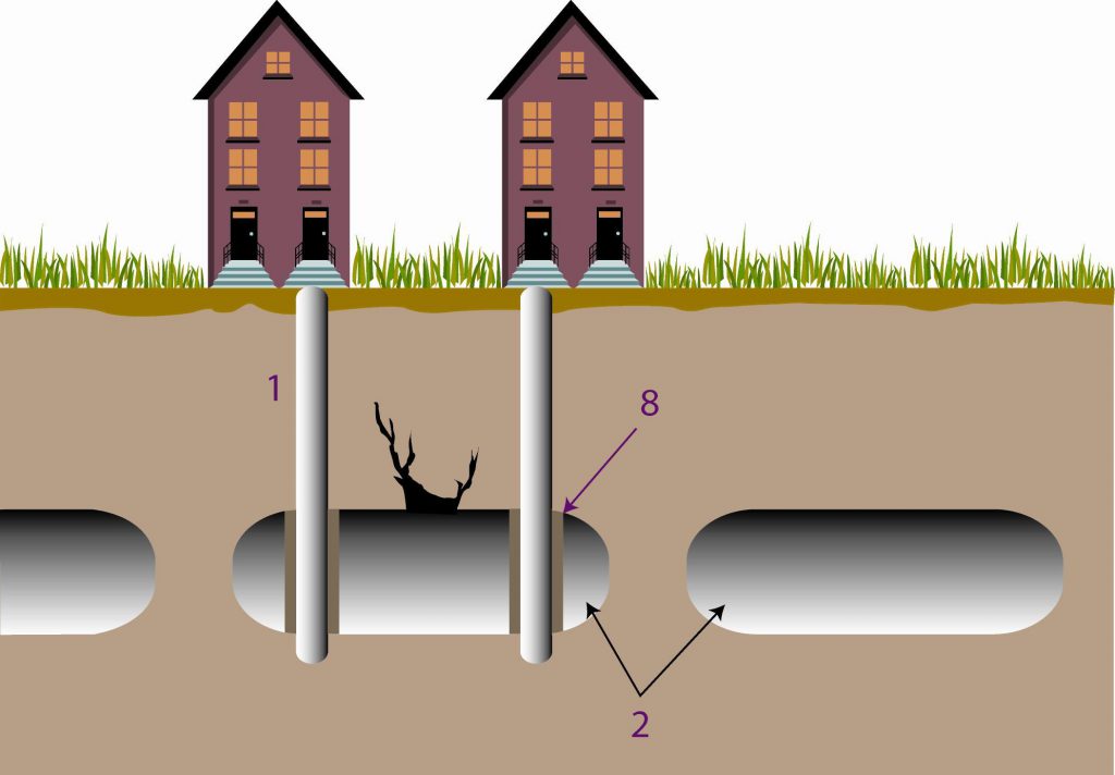
Realization of deep foundations (i.e. concrete piles), crossing the cavity, can be a means of protecting (with 1: pile; 2: natural or artificial caves; 8: casing for protection against alteration)
References
Côte, PH., fauchard, C., Pothérat, P. (2005). Méthodes géophysiques pour la localisation de cavités souterraines : potentialités et limites. In Evaluation et gestion des risques liés aux carrières souterraines abandonnées. Actes des journées scientifiques du LCPC, pp. 8-17.
Embleton, C., and Embleton C. (eds.) (1997), Geomorphological Hazards of Europe. Developments in Earth Surface Processes 5. Amsterdam : Elsevier, 524p.
Flageollet, J. C. (1988), Les mouvements de terrain et leur prévention, Paris : Masson, 224p.
LCPC (2000). Guide technique pour la caractérisation et cartographie de l’aléa dû aux mouvements de terrain. Collection ‘les risques naturels’. Laboratoire Central des Ponts et Chaussées, 91 p.
Maquaire, O., (2005). Geomorphic hazards and natural risks, In: Koster, E., A. (ed.), The Physical Geography of Western Europe, Oxford Regional Environments, Oxford University Press, Chapter 18, 354-377.
Ministère de l’Environnement, 1997, Plans de prévention des risques naturels (PPR) : guide général.. La Documentation Française, Paris, 76p.
Ministère de l’Environnement, 1999, Plans de prévention des risques naturels (PPR) : risques de mouvements de terrain. Guide méthodologique.. La Documentation Française, Paris, 71p.
Ministère de l’Ecologie et du Développement Durable, 2004. Dossier d’information sur le risque Mouvement de terrains, 20 p. (à télécharger sur site du MEDD).
Pothérat, P. (2005). L’opération de recherche « Carrières souterraines abandonnées ». Localisation, dignostic de stabilité, gestion. Rapport de synthèse. Géotechnique et risques naturels, GT 77. LCPC, 132 p.
Websites:
http://fr.wikipedia.org/wiki/Subsidence
http://www.lorraine.drire.gouv.fr/mines/g_cadreDomaine.asp?droite=2_ApresMines.asp&bas=g_MinesNavig.asp?DEST=APMINES
http://www.cgm.org/themes/soussol/mines/
http://www.cavite.net
http://www.prim.net/professionnel/documentation/dossiers_info/nat/low/mouvtTerr.pdf
http://www.catp-asso.org/cavites37/pages/missions.htm
http://clamart.cyberkata.org/
Le conseguenze di una frana possono essere mitigate attraverso metodi di protezione e di consolidamento.
Si può ridurre il rischio da frana e si può garantire una certa protezione attraverso due tipologie di interventi di prevenzione o mitigazione:
- La difesa attiva ha come obiettivo le cause del fenomeno attivo o potenziale e consiste, generalmente, nel drenaggio profondo o nella riforestazione;
- La difesa passiva ha come obiettivo i materiali mobilizzati o mobilizzabili dal fenomeno franoso, e consiste, generalmente, in opere di terrazzamento, profilatura del pendio e costruzione di strutture di ritenzione.
In casi di alto rischio, dove il livello di vulnerabilità è molto alto e non vi è modo di ridurre il livello di pericolosità, deve essere organizzato un sistema di monitoraggio. Solitamente vengono monitorati con continuità i movimenti superficiali e le variazioni del livello della falda e, al raggiungimento di una certa soglia predeterminata, viene prodotto un segnale d’allarme sonoro.
Rispetto ai processi di cedimento, di ritiro-rigonfiamento e di subsidenza, esistono in genere due tipologie di metodi di consolidamento e prevenzione tra cui scegliere, in base alla loro efficienza ed ai loro costi:
- Metodi “hard” (molto costosi, ma generalmente efficienti), che consistono nella consolidazione dell’edificio;
- Metodi “soft” (costi più bassi e spesso sufficienti), che consistono in azioni positive all’intorno dell’edificio.
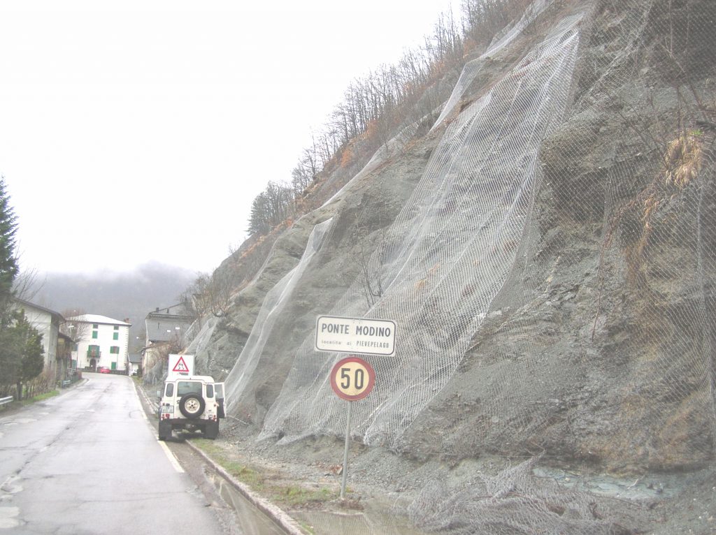
Techniques of prevention
Prevention of slides, as for landslides in general, comprises several successive stages. First, investigations must be carried out in order to identify the sectors prone to slide. These investigations lead to slide hazard assessment. Then, elements at risk are identified and their vulnerability is assessed in order to include slide hazard in town planning. The result is a zoning map which defines terrains which can be built or not, according to the degree of hazard and vulnerability (go to 12.1.More information on landslide mapping). Therefore, the town is obliged to control all water discharge (drainage waters, waste waters, rain waters) and to avoid digging being liable to destabilize the slope.
Techniques of protection
These techniques are usually used for reducing small-scale slide hazards. In large-scale and very deep slides, in combination with protection techniques such as underground drainage, the best way is to continuously monitor the site and take urban planning measures.
Techniques of protection can be classified in two distinct categories:
– “Active techniques”: they avoid the triggering of the slide. They mainly consist in increasing the strength of the slope-forming material, by drainage or internal soil reinforcement systems.
– “Passive techniques”: they seek to control the consequences of the slide. They consist in external reinforcement systems which retain the material on the slope.
A. Active techniques
– Drainage techniques
Drainage of water is the most important operation for the correction of existing or potential slides. Drainage will both reduce the weight of the mass tending to slide, and increase the strength of the slope-forming material. Surface, subsurface and underground drainage techniques exist. Figure 1 show different drainage techniques used to stabilize a slope (from TRB, 1978).
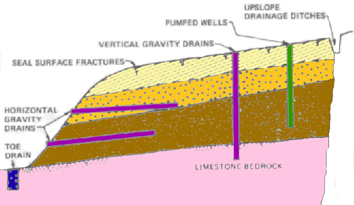
Surface drainage is strongly recommended as part of the treatment for any slide or potential slide. Interceptor drains and drainage ditches collect and carry surface waters away from the instable slope. These systems provide a rapid surface drainage. A ditch is between 0,5 and 1 metre deep, with triangular, rectangular or trapezoidal section.
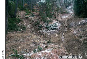
These methods to control surface runoff are effective when used in conjunction with subsurface and underground drainage techniques. It is agreed that groundwater constitutes the most important contributory cause for the majority of landslides (See 3.1.1. More details on the role of water). Thus, the most successful methods used for both prevention and correction of slides consist of entirely or partially groundwater control.
Draining trench is usually employed for subsurface drainage. The trench is 5-6 metres deep. A drain pipe perforated in its upper part is installed at the bottom of the trench. A membrane can be put, to prevent contact between backfill and surrounding material or to avoid clogging of the drain. Then, the trench is filled with pervious rock mixture, generally with clean granular material or pebbles. At the surface, the trench must include inspection holes to control functioning of the drainage system.
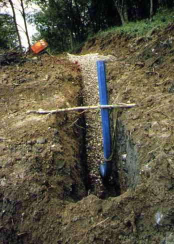
Finally, drainage waters must be collected and carry away from the unstable slope. Figure 4 shows an example of impervious collecting system.
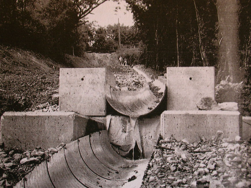
Draining trench is not efficient in case of active landslide because it can break up and is insufficient for deep landslides. Underground drainage is necessary.
Underground drainage implies boreholes drilling. It consists of subhorizontal drains, when water table is too deep to be lowered with surface or subsurface drains. When the instable mass is deep and when the movement is slow (1cm/year), vertical drains and pumped wells are used.
Underground drainage is more expensive and more difficult to accomplish than surface and subsurface drainage. Drilling operations must be carried out carefully, during dry seasons when the displacements are the slowest. Then, water table level and displacements must be monitored during one year at least.
Moreover, problems exist concerning subdrains: clogging by materials such as dispersive clays, cohesionless silts, or root system of dense vegetation. Rodents can also make homes of subdrain outlet pipes, or these pipes can become overgrown near their discharge point, causing the system to back up. Hard groundwater can deposit calcium carbonate around the percolation silts in subdrain pipes or well casings.
Finally, it is necessary to do geotechnical and hydrogeological studies before beginning the treatment, because the effectiveness and the frequency of use of the various types of drainage techniques vary according to the geology and the climatic conditions. That is why many practitioners prefer to use drainage in combination with other measures, such as retaining structures.
– Slope remodelling
Another method to stabilize a slope is remodelling. The principle is to remove the upper part of the slide by excavation and to buttress the toe of the slide by filling and compaction. This technique can be used during construction or stabilization of existing roadways slopes. But in case of natural terrains, this method is not efficient because the quantity of material necessary to remove is generally too important. However, shallow remodelling can be done.
– Role of vegetation
Vegetation has positive and negative effects on slope stability (3.1.2. More information on landslide causes>>). In many cases, planting is considered as a long-term strategy for natural hazards prevention, more particularly for slide risk management. Figure 5 shows a good example of positive effect of the vegetation on slope stability. The root network of a banyan tree stabilizes a nearly vertical cut in colluvium on a trail at Diamond Head, Hawaï. Water percolating through the colluvium serves to propagate the expanding root system. The concept of reinforced earth (see below) emanates from this kind of natural process.
– Soil reinforcement using Geogrid
Geogrid is usually used during the construction of embankments near highways, or to repair existing landslides. It corresponds to the concept of reinforced earth. The principle is to provide tensile reinforcement through frictional contact with the surrounding soil. Soil-reinforcing grids serve to increase the unit shear strength of any soil which they are placed, thereby offering much higher long-term factors of safety than are possible trough simple compaction.
The grids are an-open-mesh construction, usually composed of polypropylene or high-density polyethylene impregnated with carbon-black ultraviolet radiation inhibitors. The size of Geogrid depends on the level of intended loading once buried in the ground. Reinforcing grids are generally placed at lift separations of 0,6-1,2 metres. Embedment lengths generally vary from 1 to 1,5 times the slope height (figure 6). Soil is then spread over the mesh and compacted (figure 7). The area immediately adjacent to the free face usually requires local compaction with hand-operated vibratory equipment.
Wrapping the slope face with the grids is an option (figure 8 and 9). Face wrapping generally provides a mulch surface to resist erosion and promote planting. Vegetation serves to protect the grids from ultraviolet degradation and vandalism. It provides an aesthetic surface and also reduces erosion. Face wrapping also helps retard rodent burrowing into the slope.
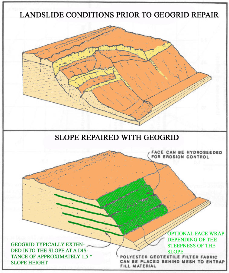
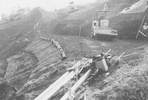
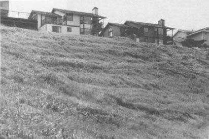
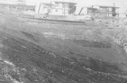
Figures 8 and 9: Two views of a Geogrid-reinforced landslide repair accomplished in 1986 in Crockett, California. The lower view shows the finished slope six weeks after completion. The slope has be hydroseeded and Geogrid face acts as a good mulch mat (from Slosson and al., 1992)
B. Passive techniques
A slope can be stabilized increasing the forces resisting the mass movement with an external applied force system. These systems usually apply a resisting force at the toe of the sliding mass. These are basically the same systems than employed for fall risk prevention: buttresses and bulkheads, retaining walls and box gabion catch walls (go to 2.1.2.2. more information on fall).
The principle of the buttress is to provide sufficient dead weight near the toe of the unstable mass to prevent moment. A buttress design provides an additional resistance component near the toe of the slope to ensure an adequate safety factor against failure. Several important highway sections have been constructed with or treated remedially by a buttress.
Care must be taken in the construction phases to ensure adequate depth for founding the buttress and prescribed quality for the layer on which the buttress is placed.
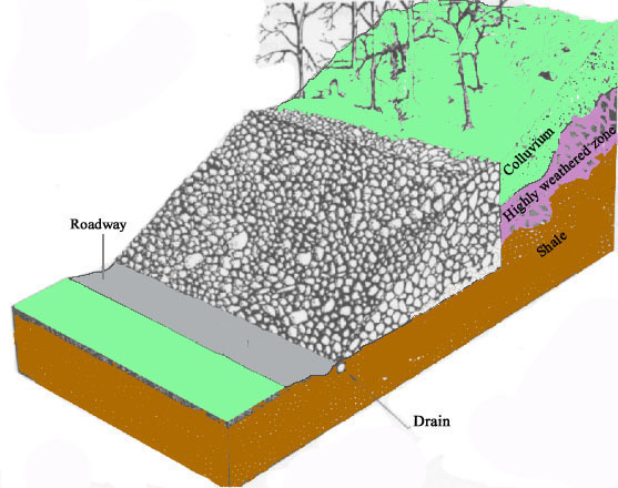
Reinforced earth wall is a construction material that involves the use of backfill soil and thin metal strips to form a mass that is capable of restraining large imposed loads. The concept is about the same than Geogrid, but the final structure is an external wall. The face of a reinforced earth wall is usually vertical, and the backfill material is confined behind either metal of unreinforced concrete plates.
As a buttress, reinforced earth wall acts as a gravity structure placed on a stable foundation, and it must be designed to resist the slope driving forces (overturning, shearing internally, sliding at or below the base).
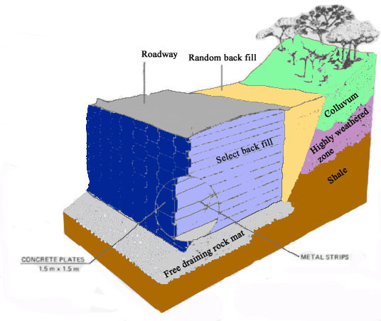
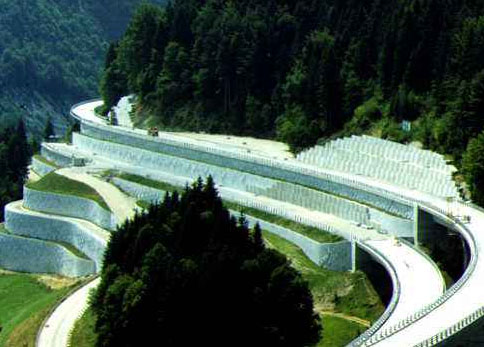
Gabion wall is also a reinforcement structure to stabilize slopes go to 2.1.2.2. more information on fall).
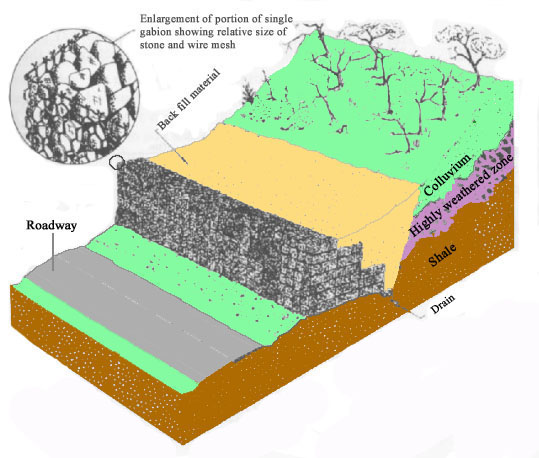
For all these reinforcement systems, it is important to create a draining backfill with pervious material upstream the structure, in order to prevent water accumulation behind the wall and negative effects on the slope.
Another retaining structure developed in 1985 by French engineers of the “Laboratoire Central des Ponts et Chaussées” is the “Arma Pneusol”, a combination of tyres, backfill and grids layers, basically to stabilize highway slopes. The structure is planted to provide an aesthetic surface. With this reinforcement system, worn tyres are also recycled.
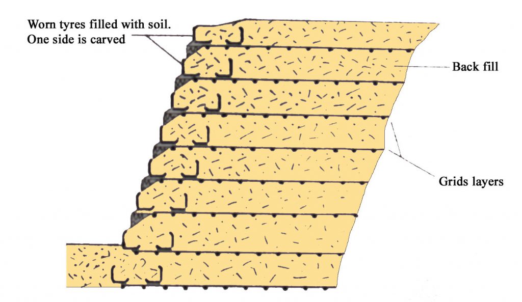
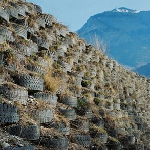
Anchor walls are also be used. The principle is the same than employed for fall risk protection techniques (go to 2.1.2.2. more information on fall). Shotcrete or retaining wall can be used in combination with passive or active anchored cables (figure 16). This protection technique is rather an “active” system, which increases the internal strength of the slope-forming material.
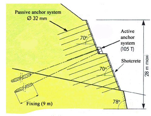
Finally, in most applications, a combination of the various methods outlined above is used. For example, soil-reinforcing grids can be mixed with any number of facing elements such as gabions, wire mesh or masonry blocks. Figures 17 and 18 show an example of rock-filled, gabion-faced embankment with Geogrid.
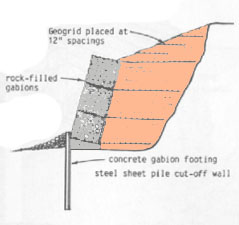
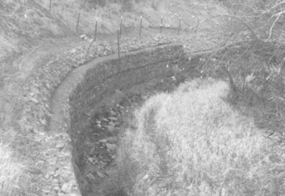
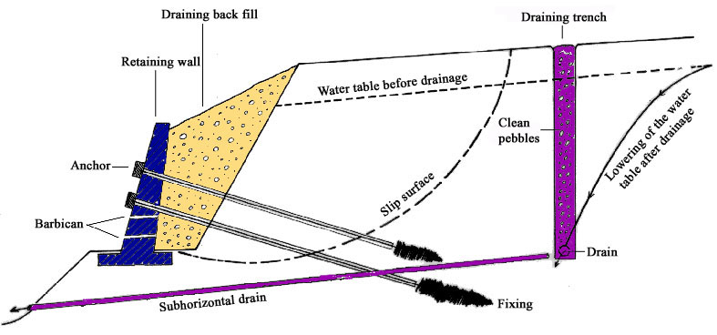
References
BESSON L., 2005. Les risques naturels: de la connaissance pratique à la gestion administrative. Editions Techni. Cités, Voiron, 60 p.
FLAGEOLLET J.C., 1988. Les mouvements de terrain et leur prévention, Masson, Paris, 224 p.
GUEFFON M., 2005. Les travaux de prévention actifs contre les glissements de terrain : stabilisation et drainage des zones instables. Risques Infos n°16, p. 13-16
SLOSSON E., KEENE A.G., JOHNSON J.A., 1992. Landslides/Landslide mitigation. In: Reviews of Engineering Geology, Volume IX, Colorado
TRANSPORTATION RESEARCH BOARD, 1978. Landslides: Analysis and Control. National Academy of Sciences, Special Report 176, Washington DC
Prevention and repairing of the damages due sinking process are in line with the techniques used to protect against the shrinking-swelling process.
Techniques of pre-consolidation of the soil by drainage and application of overload before the construction process are commonly applied.
Two types of repairing methods and prevention techniques are generally undertaken according to their efficiency and costs:
- “hard” methods (high expensive costs but generally efficient), consisting of the reinforcement of the building with piles and steeled girder, alternate piles, micro-stakes, chaining, etc;
- “light” methods (less expensive costs and often sufficient), consisting of positive actions in the surrounding of the building (control of the water discharge, control of the vegetation with root screens and the choice of adapted vegetation variety, isothermal protection of the foundations, artificial increase in soil humidity with micro-porous pumps etc…).
References:
Bekkouche N. et al., 1990. Foundation problems in Champlain clays during droughts: I – rainfall deficits in Montreal (1930-1988). Revue Canadienne de Géotechnique, vol. 27, n°3, pp. 285-293.
Bekkouche N. et al., 1992. Foundation problems in Champlain clays during droughts: II – Cases histories. Revue Canadienne de Géotechnique, vol. 29, n°2, pp. 169-187.
Biddle P.J. 1983. Pattern of soil drying and moisture deficit in the vicinity of trees on city soils. Géotechnique, vol. 33, n°2, pp.107-126.
Driscoll R. 1983. The influence of vegetation on the swelling and shrinking of clay soils in Britain. Géotechnique, vol. 33, n°2, pp.93-105.
Embleton, C., and Embleton C. (eds.) (1997), Geomorphological Hazards of Europe. Developments in Earth Surface Processes 5. Amsterdam : Elsevier, 524p.
Flageollet, J. C. (1988), Les mouvements de terrain et leur prévention, Paris : Masson, 224p.
Maquaire, O., 2005. Geomorphic hazards and natural risks, In: Koster, E., A. (ed.), The Physical Geography of Western Europe, Oxford Regional Environments, Oxford University Press, Chapter 18, 354-377.
Internet links:
http://www.prim.net/professionnel/documentation/dossiers_info/nat/low/mouvtTerr.pdf
http://www.argiles.fr/
In caso di frana, ci si può trovare in differenti situazioni: sul materiale in movimento o di fronte ad esso. Esiste anche la possibilità di incorrere in un movimento franoso durante lo spostamento con mezzi di trasporto, ad esempio, con una macchina.
Nella maggior parte dei casi, specialmente se si è di fronte ad un movimento franoso di grandi proporzioni, poco si può fare, ma vi sono alcune indicazioni generali, utili in caso di qualsiasi pericolosità naturale, che possono divenire preziose anche in una simile situazione.
In alcuni casi, le scuole sono messe in grave pericolo dalle frane, ma possono anche divenire un utile “palestra”, attraverso esercitazioni svolte negli stessi luoghi scolastici, per testare le giuste reazioni che si devono assumere in caso si verifichino eventi franosi, come indicato di seguito.
- Prima dell’evento franoso
Cerca di sapere se frane sono già avvenute, nel passato, nella tua zona, contattando gli uffici dell’Amministrazione Pubblica; contatta la Protezione Civile locale per visionare i piani di emergenza ed evacuazione per la tua zona e per predisporre il tuo piano d’emergenza personale. - Durante l’evento franoso
i) se ti trovi all’interno di un edificio (ad esempio la tua classe): a) non correre fuori, rimani dove sei; b) trova riparo sotto un tavolo, sotto una trave portante o vicino ad un muro portante; c) non utilizzare gli ascensori; d) rimani lontano dalle finestre, dalle porte a vetri o dalle credenze.
ii) se ti trovi all’esterno: a) allontanai dagli edifici, dagli alberi, dai lampioni stradali, dai cavi elettrici e dai cavi telefonici; b) non camminare o guidare lungo una strada di recente interessata da una frana; c) non ti avventurare su di un corpo di frana; d) non entrare in edifici coinvolti da una frana prima di una completa verifica da parte di esperti.

“Civil protection in family”: a booklet edited by the Italian Civil Protection containing the instruction about “what to do” in case of disasters.
- Prior to the event
- During the event
 |
Don’t rush outside, stay where you are. By staying inside the building you are more protected than outside. |
 |
Take shelter under a table, below the architrave, or near the bearing walls. They protect you from possible cave – ins. |
 |
Stay away from windows, doors with glass and cupboards. They could fall and hurt you. |
 |
Don’t use lifts. They could get stuck and prevent you from exiting. Help the other people around you. Maybe there are some people hurt or even disabled or people that are in trouble to move by themselves. Remember to help them to go out of the building when it will be safe the exit. |
 |
Move away from buildings, trees, streetlights, electric cables and telephone lines. They could fall down and hurt you. |
 |
Don’t walk or drive along a road where a landslide has recently occured. It is instable material that could start moving again. |
 |
Don’t venture out on a landslide body. The material of a landslide, even if stable in appearance, can hide dangerous underlying holes. |
 |
Do not enter inside houses involved in a landslides before a thorough assessment by experts. They could have sustained structural damage and be unsafe. |

La cartografia è spesso un passo obbligato negli studi di pericolosità da frana. Possono essere prodotte carte di base, quali le carte geomorfologiche o le carte-inventario dei fenomeni franosi, ma anche carte derivate, quali le carte di suscettività o di zonizzazione della pericolosità da frana.
- A cosa servono?
La cartografia può definirsi:
- diretta, laddove l’estensione e la distribuzione delle frane vengono identificate su base morfologica, allo scopo di estrapolare il giudizio di stabilità sull’intera area in esame;
- indiretta, quando la possibilità che si verifichi una frana viene valutata considerando o meno la distribuzione delle frane nel territorio.
La cartografia diretta si ottiene, solitamente, attraverso l’interpretazione di fotografie aeree e rilevamenti di campagna, accompagnati da ricerche bibliografiche e d’archivio.
La cartografia indiretta si basa su altri fattori (principalmente geomorfologici e geologici) che possono favorire l’occorrenza delle frane. Pertanto, queste cartografie rappresentano zone in cui vi è la possibilità che si verifichino fenomeni franosi.
Le carte-inventario delle frane sono prodotti cartografici efficaci e di facile consultazione, sia da parte di esperti, come i geologi ed i geomorfologi, sia da non esperti, compresi i decisori politici, i pianificatori ed i responsabili di protezione civile.
- Dove si possono trovare queste carte?
Le carte si possono trovare negli uffici dei servizi pubblici competenti, presso enti di ricerca ed in pubblicazioni scientifiche, riviste e libri.
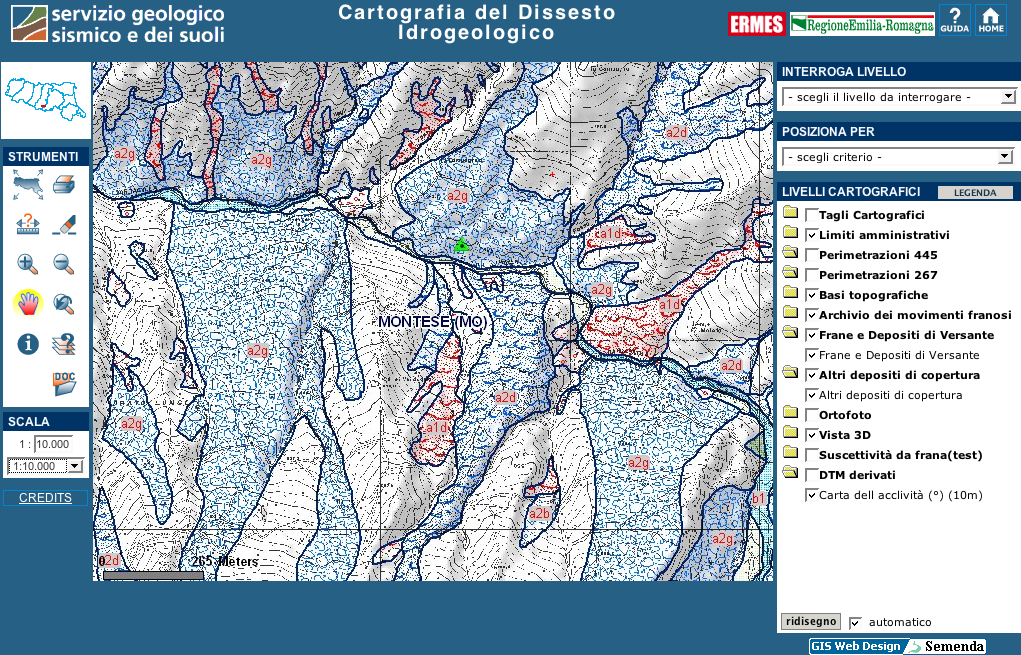
By Alessandro Pasuto1, Mauro Soldati2, & Doriano Castaldini2
1 CNR – IRPI, Padova (Italy)
2 Dipartimento di Scienze della Terra, Università di Modena e Reggio Emilia (Italy)
Mapping is often a necessary step in landslide hazard studies. Maps may consist either of basic documents such as geomorphological maps and landslide maps or of landslide susceptibility maps and hazard zonation maps. Mapping can be defined as direct, when the landslide extent and distribution are recognised on a geomorphological basis with the aim of extrapolating slope stability assessments to the rest of the investigated area, or indirect, when the possibility of landslide occurrence is assessed in relation to the controlling factors, with or without consideration of landslide distribution (Hansen, 1984).
Direct mapping is usually obtained through aerial photo-interpretation and ground surveys, which vary proportionally according to the scale adopted for the study, together with bibliographical and archive investigations. The result can be inventory maps which record landslide distribution over an area (e.g Rybár, 1973; Alger & Brabb, 1985; Guzzetti & Cardinali, 1989). Landslides inventory maps are effectively and easily understandable products fot both experts, such as geologists and geomorphologists, and for not experts, including decision makers, planners and civil defence managers (Galli et al., 2008).
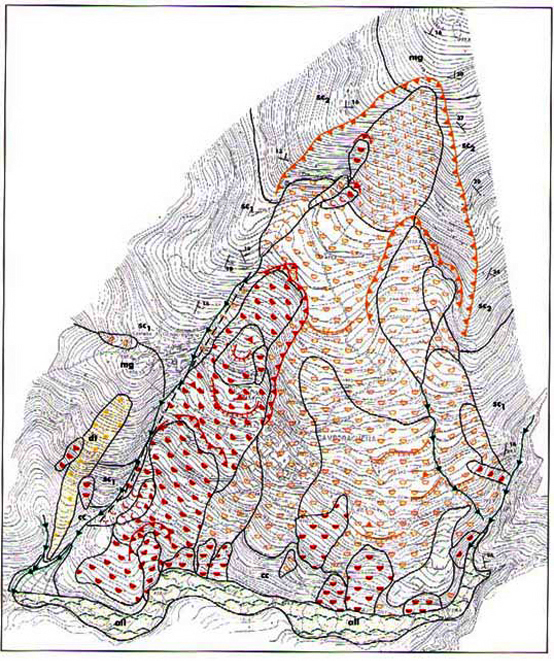
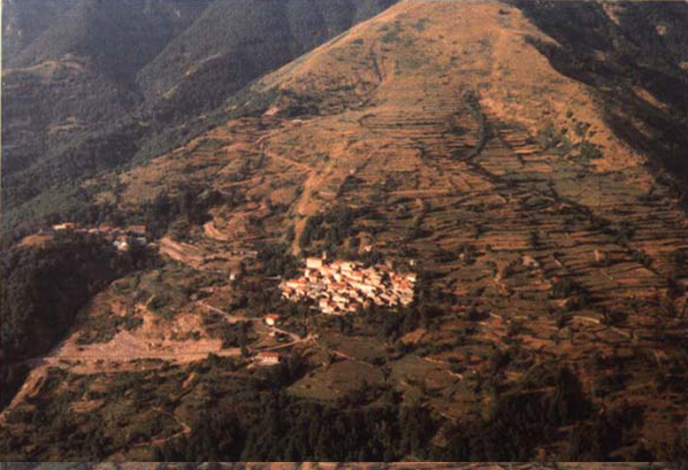
The Landslides inventory maps are generally the basis for further detailed studies aiming to assess future failures. The information contained in these maps may also include landslide type, bedrock lithology, superficial deposits, slope angles, engineering geological zonation etc.
In Italy an homogenous and updated Inventory of Italian landslides has been implemented by APAT (Geological Survey of Italy/Land Protection and Georesources Department). The Italian Inventory of landslides (IFFI) holds over 460,000 phenomena occurred in the Italian territory.
APAT published the IFFI Inventory on the Internet as well as the report on the Project (APAT 2007) with the aim of disseminating information about landslides to national and local administrations, research institutes, geologists, engineers and citizens .
Go to IFFI Inventory web site (http://www.apat.gov.it/site/it-IT/Progetti/IFFI_-_Inventario_dei_fenomeni_franosi_in_Italia/)
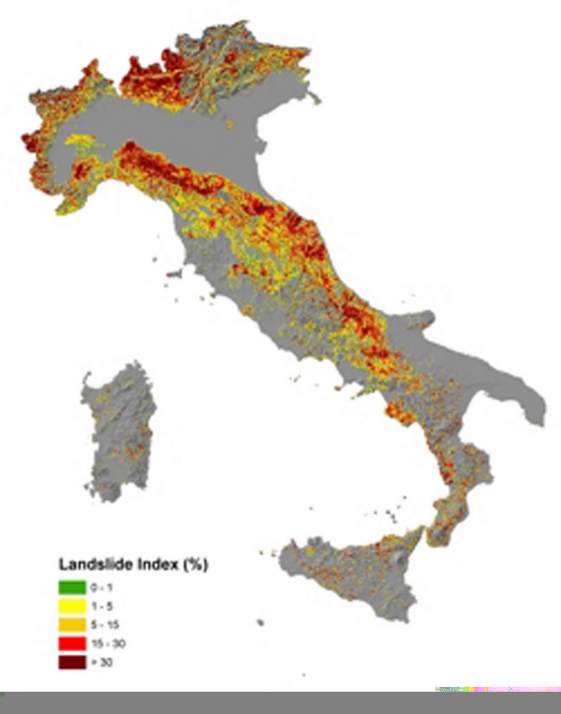
In the Emilia – Romagna Region, the Instability Inventory Maps, created on the base of traditional geological maps, have a great applied significance for territorial planning. In fact, it is forbidden to built up on “areas affected by active landslides” (landslides which are currently active or that have been reactivated since the last 30 years) meanwhile it is allowed to build up on ” areas affected by dormant landslides” (landslides that have not showed signs of activity since the last 30 years and that could be reactivated by their original causes) or on “Potentially instable areas” (quaternary deposits affected by evident superficial morphogenetic processes) only if prevenction and mitigation measures have been adopted.

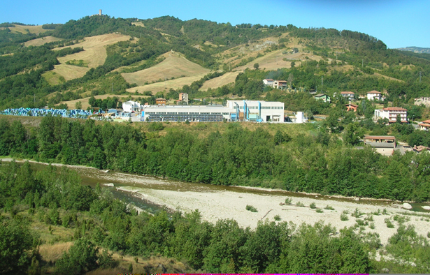
Geomorphological maps are another product of direct mapping. These are generally at a larger scale (less than 1:25,000) than those described above and form a very useful basis for landslide hazard studies since they include details on general slope morphology and related processes, and define the type of failure and degree of activity as well as the features associated with landslides. Geomorphological mapping may be easily and usefully applied to the study of mass movements.
There exist many significant examples of landslide-orientated geomorphological maps, such as that of Brundsen et al. (1975), carried out with aim of identifying landslide hazard in an area of Nepal where the construction of a road and a bridge was proposed, or that of Panizza (1990) where the landslides surrounding the town of Cortina d’Ampezzo (Italian Dolomites) are mapped in detail. An interesting attempt to include the temporal aspect in landslide mapping was made by Flageollet (1994) in the above mentioned Dolomite area. The temporal information reported on the computer-based landslide map of the area of Cortina d’Ampezzo is related to periods of activity during the Holocene and to the frequency and incidence (first time failure or removement failure) of the movements. An updating of the Panizza (1990) map has been carried out by Pasuto et al. (2005).
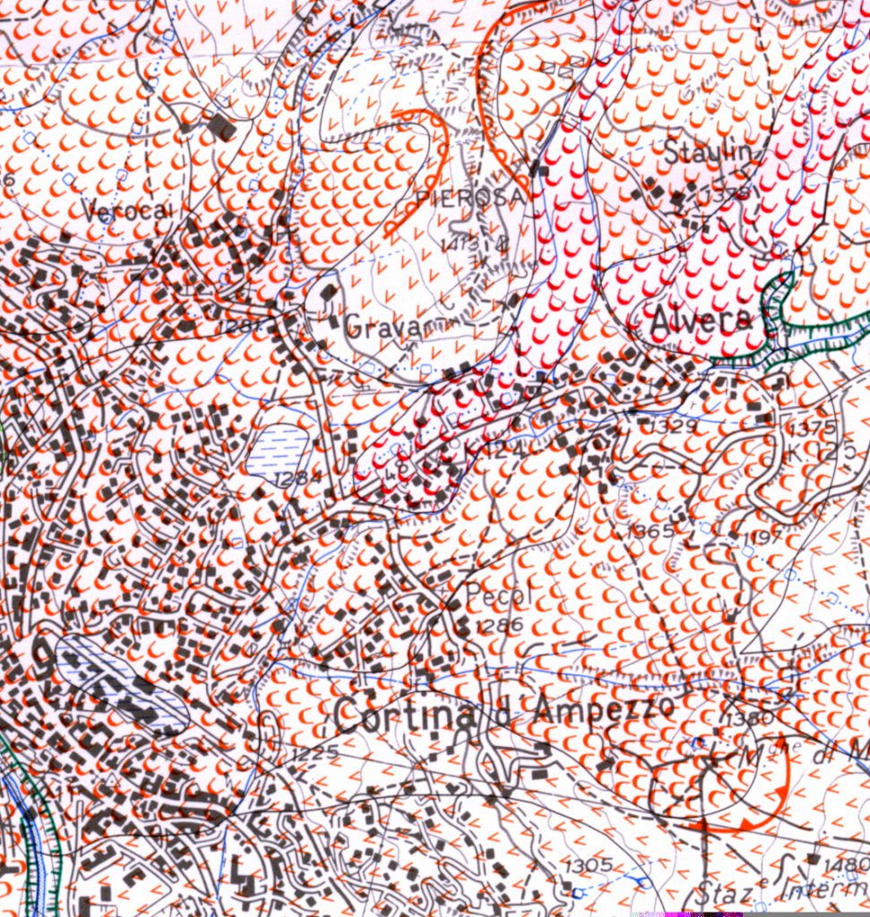
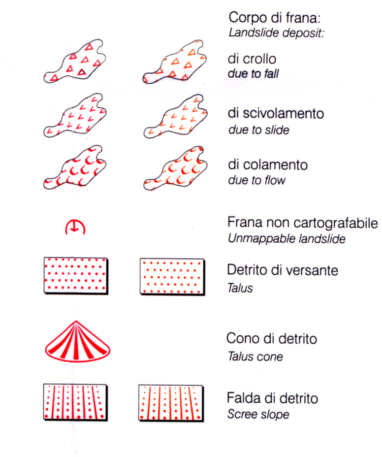

Geomorphological maps may in many cases be too complicated to be read by non-specialists. This is the reason why planners and engineers are generally provided with derivative maps which appear simpler from a purely graphic standpoint and take into account only those processes and landforms that are connected with slope instability. The product can be a geomorphologically-based landslide hazard map. Many examples, carried out according to different methodologies, are known in literature. The first example should refer to the French ZERMOS (Zones Exposées aux Risques de Mouvement du Sol et du Sous-sol) hazard maps which have been produced for several sample areas at a scale 1:25,000. The hazard (actual and potential) is assessed and rated taking into account distribution of landslides, evidence of instability, as well as geological, geomorphological and hydrological aspects.
Another significant example is provided by Kienholz (1978) who carried out a study in the Grindenwald, an area of the Swiss Alps affected by mass movements and avalanches; first a geomorphological map was produced and from this a natural hazard map was obtained. The degree of hazard was assessed for a high number of previously defined geomorphological units using checklists.
When the casual factors of landslides can be recognised, measured and mapped and the analysis of the distributions of the different factors controlling landsliding can be made, indirect mapping can be carried out.
An original method aiming at the elaboration of hazard susceptibility maps has been defined and tested in a few sites in Italy and has been adopted by the National Geological Survey as the official procedure for the compilation of geological hazard maps (Amanti et al., 1992). This method includes both indirect and direct mapping procedures. In fact, this approach consists, on the one hand, of the analysis of the causes of instability (ascribable to both slope and fluvial processes) which are outlined in a series of thematic maps (geological, hydrogeological, vegetational etc.) and weighted by means of specific procedures, with the aim of producing a first derivative map (integrated analysis map) depicting the distribution of potentially unstable areas. On the other hand, by means of geomorphological investigations, the analysis of the effects of instability is carried out in order to give an outline of landforms and processes, both active and inactive, referable to geomorphological instability. The cartographic documents produced during this phase are a geomorphological map and a second derivative map (map of geomorphological dynamics) showing the areas which are at present unstable. The comparison and critical discussion of these two derivative maps lead to the production of a “geomorphological hazard map”, a concise document depicting present and potential unstable areas subdivided according to the causes of instability.
A partly similar approach was used for research on landslide hazard in Tuscany (Italy) which led to the elaboration of several landslide maps, accompanied by geological information permitting the assessment, albeit qualitatively, of the ratio between the degree of stability attributed to an area and its structural characteristics. In these hazard maps the following categories are distinguished: highly hazardous areas, including active and dormant landslides, areas characterised by high potential instability linked to the morphological aspects, areas prone to landsliding owing to lithological aspects, areas of medium stability and finally stable areas (Nardi et al., 1985).
Jones (1992) refers to a further approach, Land Systems Mapping, which is placed among indirect mapping techniques and is based on the subdivision of the study territory into limited areas (land systems, land units, land elements, passing from large scale to small scale subdivisions) in which predictable combinations of landforms, soils, vegetation and superficial processes take place. This approach, created with the goal of producing basic maps for rural planning, has been extremely useful in landslide hazard assessment since it allows large portions of territory to be quickly classified providing a useful regional picture for data collection and storage.
In the last decade many other methods has been proposed for the assessment of landslide hazard and risk all over the world (e.g. Heinmann et al.. 1998, Raetzo et al., 2002; Santacana et al., 2003; Zezerè et al. 2004; Guzzetti et al.. 2005) because the quantification of risk has gained importance in many disciplines. Anyhow the problem of attempting to quantify landslide hazard and risk is still difficult to solve (Cascini et al. 2005, van Westen et al., 2005).
In Italy, the zoning of areas subject to hydro-geological risks has been regulated since 1998 by a specific law and its associated application decree, which were released after the “Sarno” mudflow disaster (go to 13.2. Sarno study case). However, these juridical documents contain only some general guidelines for a common working methodology to be adopted for hydro-geological risk assessment in all of the Italian territory, and leave Basin Authorities free to define their own specific guidelines and, upon will, involve in this process research institutions and private consultants. This led to a large differentiation of procedures among Basin Authorities, and in practice the only standards adopted nation wide regard the work steps to be adopted, the goal of the investigation (that is the subdivision of risk in 4 classes) and the constrains to be adopted on high risk zones in terms of land use limitation and land management policy.
In particular, the risk zoning was calibrated according to the 4 risk classes defined by the Central Goverment as follows:
i) Very high (R4): human life loss and destruction of buildings, infrastructure and environmentall as well as interruption of economic activities are expected;
ii) High (R3): victims, functional damage to buildings and infrastructure, as well as partial interruption of economic activities are possible;
iii) Medium (R2): limited damage to buildings, infrastructure and environmentalmay occur;
iv) Low (R1): social, economic and environmental damageare of marginal relevance;
The results obtained for the territory of the National Authority of Liri – Garigliano and Volturno river basin (a territory of about 12,000 km2 located in Central-Southern Italy) are summarized in the following (Cascini, 2005). Inside the study area, undeveloped areas affected by dormant, active or potential landslides were mapped and classified according to the risk classes defined and the Cruden and Varnes (1996) suggestions; these areas were considered worthy of different attention levels.
To zone the risk and attention areas, geological, geomorphological and soil cover maps were preliminarily compiled. Subsequently, using these maps as well as aerphoto interpretation and available informations, 30,000 landslides together with their surroinding areas, and zones potentially affected by fast slope movements were mapped using Varnes (1978) classification, creep evidence, state of activity and other criteria described by Cascini (2005)(Fig.8).
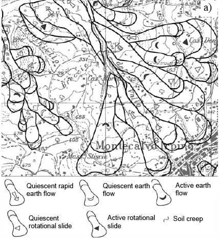
Starting from these data, danger maps were then implemented by adopting velocity estimates as well as of the source and propagation areas potentially affected by first stage movements (Fig.9).
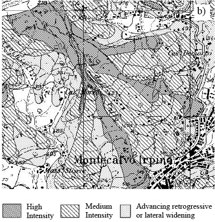
Simplified hazard maps as well as simplified vulnerability maps for all the towns (450) were produced. Referring to the Varnes’ formula, the risk classes (Fig. 10) were obtained by overlapping hazard and vulnerability maps. An example of map containing the attention and risk classes previously defined is shown in Fig. 11.
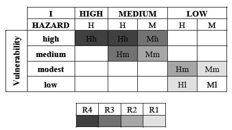
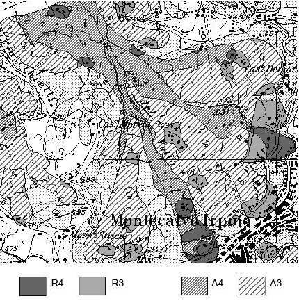
References
Alger, C.S. and Brabb, E.E., 1985. Bibliography of United States landslide maps and reports. US Geological Survey Open-File Report, 85-585, 119 pp.
Amanti, M., Carrara, A., Castaldo, G., Colosimo, P., Gisotti, G., Govi, M., Marchionna, G., Nardi, R., Panizza, M., Pecci, M. and Vianello, G., 1992. Linee guida per la realizzazione di una cartografia della pericolosità geologica connessa ai fenomeni di instabilità dei versanti alla scala 1:50.000 (versione preliminare). Servizio Geologico Nazionale, Roma, 53 pp.
APAT (2007) – Rapporto sulle frane in Italia. Il Progetto IFFI – Metodologia, risultati e rapporti regionali. Rapporti 78/2007, 680 pp.
Brunsden, D., Doornkamp, J.C., Fookes, P.G., Jones, D.K.C. and Kelly, J.M.H., 1975. Large scale geomorphological mapping and highway engineering design. Quart. J. Engng. Geol., 8: 227-253.
Cascini L,, 2005. Risk assessment of fast landslides – From theory to practice. General Report. Proc. of the Int. on “Fast Slope Movements – Prediction and Prevention for Risk Mitigation”, Napoli, Vol. 2. Patron Editore.
Cascini L,. Bonnard C., Corominas J., Jibson R. and Montero-Olarte J. 2005. Landslide hazard and Risk zoning for urban planning and development. Proc. of the Int. Conf. on Landslide Risk Management, Vancouver 31 may-3 june 2005, pp. 199-235, Ed. Balkema,
Cruden, D.M. and Varnes, D.J., 1996. Landslides Types and Processes. In: A.K. Turner and R.L. Schuster (Editors), Landslides: Investigation and Mitigation. Transportation Research Board, National Academy of Sciences, Washington D.C., Special Report 247, pp. 36-75.
Flageollet, J.-C., 1994. The time dimension in the mapping of earth movements. In: R. Casale, R. Fantechi and J.-C. Flageollet (Editors), Temporal occurrence and forecasting of landslides in the European Community. Final Report, European Commission, Bruxelles, 1, 7-20.
Galli M., Ardizzoni F., Cardinali M, Guzzetti F. and Reichenbach P. (2008) – Comparing landslide inventory maps. Geomorphology 94, 268-289.
Guzzetti, F. and Cardinali, M., 1989. Carta Inventario dei Fenomeni Franosi della Regione dell’Umbria ed aree limitrofe. G.N.D.C.I. Pub. n. 204. Map at 1:100,000 scale.
Guzzetti, F., Reichenbach, P., Cardinali, M., Galli M. and Ardizzone F., 2005. Probabilistic landslide hazard assessment at the basin scale. Geomorphology 72, 272-299.
Hansen, A., 1984. Landslide Hazard Analysis. In: D. Brunsden and D.B. Prior (Editors), Slope Instability. Wiley & Sons, New York, pp. 523-602.
Heinimann H.R., Holtenstein K., Kienholz H., Krummenhacher B. & Mani P., 1998. Methoden zur Analyse und Bewertung von Naturgefahren. Umwelt-Materialien Nr. 85, Naturgefahren, BUWAL, Bern, 248 pp.
Jones, D.K.C., 1992. Landslide hazard assessment in the context of development. In: G.J.H. McCall, D.J.C. Laming and S.C. Scott (Editors), Geohazards. Chapman & Hall, London, pp. 117-141.
Kienholz, H., 1978. Maps of geomorphology and natural hazards of Grindenwald, Switzerland, scale 1:10,000. Arctic and Alpine Res., 10: 169-184.
Nardi, R., Pochini, A., Puccinelli, A., D’Amato Avanzi, G. and Trivellini, M., 1985. Valutazione del rischio da frana in Garfagnana e nella Media Valle del Serchio (Lucca). 1) Carta geologica e della franosità degli elementi “Gragnana”, “Piazza del Serchio”, “Casciana” e “Caserana” (scala 1:10.000). Boll. Soc. Geol. It., 104: 585-599.
Nardi R., Pochini A. & Allagosta M. (1990), La frana di Camporaghena (Lunigiana). Struttura del sistema di monitoraggio e risultati preliminari. Proceedings of the GNDT Meeting “Zonazione e riclassificazione sismica”, Pisa, 443-460.
Panizza, M., 1990. The landslides in Cortina d’Ampezzo (Dolomites, Italy). Proc. ALPS 90 – 6th ICFL, Switzerland-Austria-Italy, Aug. 31st-Sept. 12th, Università degli Studi di Milano, pp. 55-63.
Pasuto A., Soldati M. & Siorpaes C. (2005) – Carta Geomorfologica dell’area circostante Cortina d’Ampezzo (Dolomiti, Italia). Carta a scala 1:20.000, S.E.L.C.A., Firenze
Provincia Di Modena (2006), Piano Territoriale di Coordinamento Provinciale, Variante di adeguamento in materia di dissesto idrogeologico ai Piani di Bacino dei fiumi Po e Reno (adottato con deliberazione del Consiglio Provinciale n°16 del 22/02/2006). Area programmazione e Pianificazione Territoriale, Area Ambiente e Sviluppo Sostenibile.
Raetzo H., Lateltin O. & Tripet J.P., 2002. Hazard assessment in Switzerland – Codes of Practice for mass movements. Bulletin of Engineering Geology and the Environment, 61, 263-268..
Rybár, J., 1973. Representation of landslides in engineering geological maps. Landslide, 1: 15-21.
Santacana N., De Paz A., Baeza B., Corominas J., Marturi J. 2003. A GIS-based multivariate statistical analysis for shallow landslide susceptibility mapping in La Pobla de Lillet area (Eastern Pyrenees, Spain). Natural Hazards 30 (3): 281-295.
Van Westen, C.J., van Asch T.W.J. and Soeters R., 2005. Landslide hazard and risk zonation – why is it still so difficult?. Bull. Eng. Geol. Env.
Varnes, D.J., 1978. Slope movements: types and processes. In: R.L. Schuster and R.J. Krizek (Editors), Landslides: Analysis and Control. Transportation Research Board, National Academy of Sciences, Washington D.C., Special Report, 176, pp. 11-33.
Zezerè J.L., Rodrigues M.L. Reis E., Garcia R., Oliveira S., Vieira G., Ferreira A.B. 2004. Spatial and temporal data management for the probabilistic landslide hazard assessment considering landslide typology. In. Lacerda W. et al (ed.) – Landslides. Evaluation & stabilization. Vol.1. pp 117-125.